Muleh
Newbie level 2
i am working on my project that switches off and ON home appliances using an android app that creats sms .The app can also request for power being drawn by the appliances through sending texts request that can be red by a gsm module. My gsm module is linked to a pic 18f4550 and my gsm module is a sim 300 gsm module. I am using a CTL6vz current sensor to measure current being drawn by each appliance and will multiply by 230v to get power being consumed by each. I will be controlling 5 appliances . Now that i have finished creating and testing my android app , my challenge now is coding a programme for a pic 18f45550 that will do the below executions.
Main components
PIC18F4550 LEDs (to show signal output) assigned to differnt pins
4 current sensors (ctl6vz) 4 relays
GSM SIM 300 ULN 203A (relay drivers)
Max 232 Terminal blocks
Appliances to be used
Light bulb (100w) by 2
Water heater
Iron and a fan
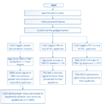
the attached pics show the commands to be sent and received using app , and the system has to contain a restart button that will alow the other program 2 to run ( the program containing the auto switch off system)
My request is a code in either C, C++ OR assembly language and a circuit diagram for the hardware.
Things to note
each signal sent goes is acknowledged by an led on another pin so as to show that a signal has been sent .
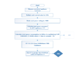
the CTL6VZ sensor produces a max output voltage of 3.3v and has a resolution of 3.2mv. It can measure upto 15A .
the programme 2 is the one that does automatic switching off after a certain amount of power has been consumed as mentioned in the pictures.
Main components
PIC18F4550 LEDs (to show signal output) assigned to differnt pins
4 current sensors (ctl6vz) 4 relays
GSM SIM 300 ULN 203A (relay drivers)
Max 232 Terminal blocks
Appliances to be used
Light bulb (100w) by 2
Water heater
Iron and a fan
the attached pics show the commands to be sent and received using app , and the system has to contain a restart button that will alow the other program 2 to run ( the program containing the auto switch off system)
My request is a code in either C, C++ OR assembly language and a circuit diagram for the hardware.
Things to note
each signal sent goes is acknowledged by an led on another pin so as to show that a signal has been sent .
the CTL6VZ sensor produces a max output voltage of 3.3v and has a resolution of 3.2mv. It can measure upto 15A .
the programme 2 is the one that does automatic switching off after a certain amount of power has been consumed as mentioned in the pictures.