Continue to Site

Welcome to EDAboard.com

Welcome to our site! EDAboard.com is an international Electronics Discussion Forum focused on EDA software, circuits, schematics, books, theory, papers, asic, pld, 8051, DSP, Network, RF, Analog Design, PCB, Service Manuals... and a whole lot more! To participate you need to register. Registration is free. Click here to register now.

High speed board to board connection

Status
Not open for further replies.
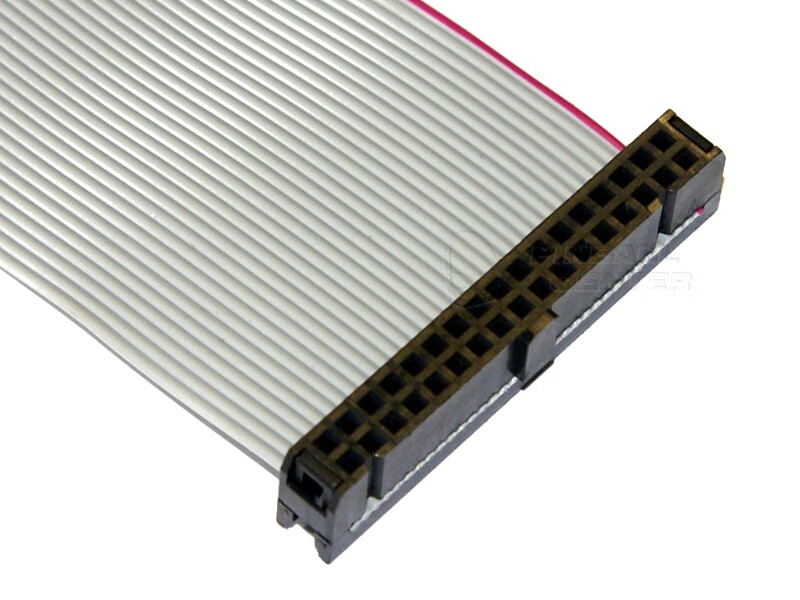
Not grounding the ribbon cable will result in very large ground loops as the signals crossing over the ribbon cable will have NO return path except through your power supply ground.

I'm not sure you are reading good papers on grounding if they suggest doing what you seem to be proposing.

To avoid miscommunicating.. Not to be stubborn, im really trying to learn here.

board.png

aesthetically I would prefer to do this. In the light of the papers I feel this would not be terribly wrong?
 
Last edited:

Thats pretty horrible actually.

Ignore the termination resistor, it is not interesting for this.

The current you need to worry about flows in the loop from the output driver on the origin board to the destination chip, then to the ground plane via the chip, then back to the origin board ground plane and eventually (via the decoupling cap and supply rail) closes the loop to the output driver.

Your star arrangement forces that current between the two ground planes to follow a much longer then is good path, interleaved grounds on the ribbon cable minimise the loop area and thus minimize both the loop inductance and the radiated field (which minimizes interference).

We have a word for a wire only connected at one end, that word is 'aerial'.....

I would seriously source terminate (100 ohms or so) to lower the edge rates and not bother with any special termination on the DAC board, SCLK is a few MHz and LRClk is less then 200KHz, these are not frequencies that need very special handling.

4 layers, buried ground and power, digital stuff at one side, analogue stuff at the other, solid ground plane, interleaved earth lines on that ribbon, it will be fine (I do mixed signal audio for a living, in reality DACs are just not that critical, unlike say microphone impedance converters.....).

Star earthing is fine at wiggly DC, it does not work above a few tens of KHz.

Regards, Dan.
 

Which part did you understand about ?
"The most common parallel interface cable was used on all HDD's before SATA was 100 Ohms unbalanced interleaved grounds
Without interleaved grounds, the signal will have more crosstalk and less capacitance to ground making it ring instead of a controlled impedance.

Ok so if I understand correctly I can pull up the signal, and return through the cable. Without grounding the cable at all. In return tying both boards to a common potential?

Yes I think pulling it up will be good enough. .

Depends on distance, which you have not specified yet.
 

From: http://www.hottconsultants.com/techtips/split-gnd-plane.html
I got this,

"A PCB with a single ground plane, partitioned into analog and digital sections, and discipline in routing the signals can usually solve an otherwise difficult layout problem"

Which yields some questions regarding my design. 1: is there "more" stuff to read about this discipline in routing?
and 2: If I route from PSU to logic to DAC, ground from my PSU will be in my logic and over the ribbon cable to my DAC to ground. Alternatively if I route down to my PSU ground from my DAC 12V and my crystal oscillator will be over the flatcable on my logic and PSU. Does routing discipline provide answers to these problems. Or is it safe in cases to use multiple paths to ground for instance?

I am biassed in favor of pulling my signal up to the DAC tho.

The datasheet from the DAC does not state when i'm not using the PCM input I should pull it down. Aren't these fed and grounded from the DAC power line, i.e. isolated from the pin?
 

After condensing it a bit.. I'm thinking about this.. Would this make sense?

panels.png

I notice now the points on the audio out, offcourse not ment to be connected..
 

If you stick to industry standard solutions as I pointed out for EDIE (PATA) HDD, you will find (free) cables that work with headers and interleaved grounds.
6114764600_1441988947.jpg

3859667100_1441988980.jpg


Using 74HC drivers (50R) it is better to use an R ladder like 220 up/330 down for 132 Ohm termination as a potential best compromise to attenuation and ringing. ( better than pullup only which degrades Vol margin. but improves Voh)

For 74ALV drivers (25R) you may need a series resistor of 82~200 Ohm depending on load with R network termination.

R network choices can be optimized once Tx and Rx chips are chosen.

Here are some options in THT
https://www.digikey.com/product-sea...=0&page=1&quantity=0&ptm=0&fid=0&pageSize=500
THere are also SMT.
 

Nice, the cyclone3/5's can do the "3.3 V LVTTL/3.3 V LVCMOS" and the minimum max voltage on the DAC is 2.2V.
So probably 3 volts is a better setting to get the signal across. Needs some checking into again before I can confidently put the voltage across the terminator.

Also I really appreciate everyone that has posted to this topic so far. It has left me saturated but confident I understand better what's going on. So.. Thanks!

Also the Learn EMC tutorials are a good source of layout information, liked the video's so far.
 

LVTTL buffers are typically capable of Vol=0.5V @24mA or 0.5/0.024= 20R drive impedance. So with 100R cable, to reduce ringing, 50~82R is desirable in series and may be increased to 200R.

But some are Vol=0.4V @8mA or 50R so 50R in series is optimal.

Vol= output low
Vih = input high
etc

LVTTL Rx threshold ~ 1.4V

example calculations


  • Assume Tx Vol,Voh= 0,3.3 with 50R internal (RdsON)


  • to Zo=100R cable to 3.3V Rx LVTTL
  • logic thresh=1.4 (asymmetric, not Vcc/2)
  • Voh spec>=2V ( for ~0.6V margin)
  • Vil spec<=0.8V ( for ~0.6V margin)


Choosing 100R equivalent load gives more margin and matched termination.

Choose Rx voltage ratio = 1.4V for R network bias
A worst case Rx Vc of 3V is almost 50% where 3.3V is 42% or around 220Rup/180dn to Rx gives 99 R (Norton equiv) and 1.5Vavg

So you can see termination impedance biased to threshold is a tradeoff of no overshoot and attenuated signal.

Depending on clock period, and cable length determines ripple time from mismatch so designing for perfect match is a tradeoff for textbook waveforms and good ripple immunity.

You could consider anything from 220R / 180R or slightly higher with same ratio termination to 3.3V / 0V respectively

Single pullup of 510R or nothing works in short distances only and depends on cable impedance may work but with less noise immunity from external impulse noise currents ( inductors, motors, cap discharge etc)
 

Be a little careful with the cyclone series and 3.3V, the pin drivers really do not like overshoot (It is mentioned in the manual).

Also, watch the requirements on the pre driver supply voltage, as memory serves there are some subtleties depending on what the IO bank voltage is).

Finally remember to connect the battery terminal on a cyclone V, even if not using the crypto stuff, the thing will not boot without it (Ask me not how I know).....

Regards, Dan.
 

Status
Not open for further replies.

Part and Inventory Search

Welcome to EDABoard.com

Sponsor

Back
Top