hamlet_jones
Newbie level 2
I've been working for weeks/months on a simple bench supply. I've learned quite a few things that don't work, and better ideas, constantly starting over, bread-boarding, etc. What I want to accomplish is a simple linear bench supply with current and voltage regulaton, <30v, <7A. Once I have accomplished this, I want to explore LM723, L200, LT1083, dual tracking, and switching supplies. I know that 7A is a tall order, but I have already built, and fried, an LM317 based voltage/current supply(back EMF), so I want something more robust. It doesn't have to be efficient. I don't care about efficient at this stage of my learning. I'll include output protection diode this time around, promise. This is my sketch, plan:
First stage is the transformer: 10A/26v, diode bridge, caps.
Second stage: mosfet voltage pre regulator.
Third stage: CURRENT ADJUST circuit.
Fourth stage: LM338.
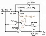
The third stage is what I am working on. I copied a portion of a circuit I found online, and it
seems to work well, with very fine control. I can light a couple of 12v/35w halogens at full intensity,
or, I can gently creep up on an LED. I mounted the twin TIP102 to a cpu heatsink.
Here is the original circuit, and the portion I removed, and modified.

I'm just working with the current portion. Here is my schematic, with mods:

If there is a better way, or if there seems to be problems, I sure would appreciate any feedback.
Maybe I need to place the current regulation before or after the pre regulation, or LM338?
First stage is the transformer: 10A/26v, diode bridge, caps.
Second stage: mosfet voltage pre regulator.
Third stage: CURRENT ADJUST circuit.
Fourth stage: LM338.
The third stage is what I am working on. I copied a portion of a circuit I found online, and it
seems to work well, with very fine control. I can light a couple of 12v/35w halogens at full intensity,
or, I can gently creep up on an LED. I mounted the twin TIP102 to a cpu heatsink.
Here is the original circuit, and the portion I removed, and modified.

I'm just working with the current portion. Here is my schematic, with mods:

If there is a better way, or if there seems to be problems, I sure would appreciate any feedback.
Maybe I need to place the current regulation before or after the pre regulation, or LM338?
