Continue to Site

Welcome to EDAboard.com

Welcome to our site! EDAboard.com is an international Electronics Discussion Forum focused on EDA software, circuits, schematics, books, theory, papers, asic, pld, 8051, DSP, Network, RF, Analog Design, PCB, Service Manuals... and a whole lot more! To participate you need to register. Registration is free. Click here to register now.

moved- FPGA based control of BLDC Motor (BLDC , FPGA , ADC , IGBT , MOSFET , 3 Phase)

Status
Not open for further replies.

umargill

Junior Member level 1
Joined
Oct 3, 2010
Messages
18
Helped
0
Reputation
0
Reaction score
0
Trophy points
1,281
Location
Daejeon, South Korea
Activity points
1,443
View attachment Three Phase Bridge IC Super Best.PDFView attachment MAXON EC 40 BLDC Motor.pdf FPGA BLDC 2.jpg

Respected All Readers and Electronics Experts,

Hello and a Good Day to all of you.

Its my 4th or 5th post on EDA Forum ever since I joined it. Fortunately, I always found excellent solutions to my queries, hence my experience here has been excellent and I hope for the same this time again.

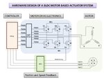
This time, as the subject of this thread illustrates, me and my team intends to monitor and control the motion of a BLDC (Brushless DC) Motor using a FPGA. Our team comprises of two sections, with the one dealing in Digital Aspects (FPGA / Motor Controller) while me responsible for selecting hardware components in Analogue domain (Motor, Motor Drive Electronics, ADC).

The BLDC Motor should have the following properties: Power(<=120 Watt), Speed (10,000 RPM), Feedback (Sensored/ Hall Effect).

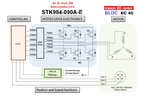
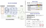
(A) I have selected a MAXON EC 40 BLDC Motor datasheet of which is attached here. It has Power(<=120 Watt), Operating Voltage (24 Volt), Speed (10,000 RPM) and Built-In Feedback (Sensored/ Hall Effect).
(B) I have also selected a Three Phase Bridge IC manufactured by On Semiconductors (STK984-091A-E)
(C) The ADC as shown in the attached picture is yet to be selected. The purpose of this ADC is to receive analogue output from Motor's Hall Effect Sensors, convert it to digital format and then feed into the FPGA.
(D) The FPGA (NOT my Part in this project) will receive the digital signal from ADC, determine the position and speed of the rotor, and will then issue PWM signals required to run the motor at any specific speed.

Now what are my Questions?

(A) Using your expertise, please VALIDATE the integration of the two components I selected so far i-e Motor and the Drive Electronics. You may also suggest me some other alternatives.
(B) Please suggest me an ADC Chip that may fit into this system.
(C) Is my approach CORRECT?
(D) It will be a great help if somebody reply me with a fully functional system based on His/Her Experience. In this case, you can simply type the names of the components into the image attached with the name (Your Design).

Thanking you in advance for viewing this thread and I will highly appreciate your input in this project.

Regards:

Umar Shafiq
PhD Student
Aerospace Engineering Department
KAIST, South Korea
 

Attachments

  • Your Design.jpg
    Your Design.jpg
    127.7 KB · Views: 172

Are you sure that the Maxon EC40 motor exposes analog hall signals? Most BLDC motors have in fact digital hall sensors, I don't see an analog sensor option offered in the Maxon catalog. In this case, the ADC channel reduces to a single channel measurement.
 
Hi,

The purpose of this ADC is to receive analogue output from Motor's Hall Effect Sensors, convert it to digital format and then feed into the FPGA.
are you sure the hall sensor output is analog? My BLDC motor has digital hall sensor outputs. It doesn´t need an ADC.

But we use an ADC for surrent sensing.
You showed to measure bridge GND currrent. We decided to measure three phase string current.

Klaus
 
I appreciate your input and I am thankful for the wise words. The matter is that this is the first time that I am dealing with HALL EFFECT SENSORS. In the datasheet of the motor, it is given as

green VHall 4.5 ... 24 VDC
blue GND
red/grey Hall sensor 1
black/grey Hall sensor 2
white/grey Hall sensor 3

I dont know what it means. I take it as a simple ON and OFF. So lets suppose that for any particular position, We have a 5V DC Voltage appearing upon one wire indicating Hall-ON, we can not directly input this to an FPGA Pin until we digitize it to suitable level for FPGA (if I am not wrong). Please share your words.

Also tell me, whether it is correct to integrate STK984-091A-E (Drive Electronics) with Maxon EC-40 (BLDC Motor)?
 

Thanks. I am agreed to your comment about current sensing. However, if you look at the motor datasheet, how can I directly input the output of hall sensor into the FPGA without converting it to suitable voltage format for FPGA?
 

Hi,

However, if you look at the motor datasheet, how can I directly input the output of hall sensor into the FPGA without converting it to suitable voltage format for FPGA?

In the simplest way your FPGA inputs are 5V tolerant.

If not: What about using a simple two resistor voltage divider at each hall signal?

Klaus
 
Every BLDC motor position sensor I've seen has had digital outputs. I'm not saying that it is impossible that the outputs are analog, only that it is unlikely.

If it were the case though that it does indeed have analog outputs, the easiest would be to condition them with a schmitt trigger device, like a 74HC14.
 
OK. That Sounds pretty nice.
May you please share your views whether it is technically feasible to join given BLDC Motor with given Drive Electronics IC?
 

The STK984-091A-E datasheet indicates a 20 amp current. So yes, it should be feasible.

This driver is a Sanken product....weird that OnSemi is now offering it. I was under the impression that Allegro Semiconductor was the one who had partnered with Sanken.
 
For respected KlausST

Please suggest me a suitable ADC IC, which may be used for current sensing in this application. 10 Bit resolution would be sufficient.
 

Hi,

Please suggest me a suitable ADC IC, which may be used for current sensing in this application. 10 Bit resolution would be sufficient.

I try.
Maybe bridge GND current is sufficient (it depends on your application and your needs), then you should go this way.
For bridge GND sensing I recommend to use a ground current sensing shunt. Low ohmic and low inductive.
Then use an OPAMP to meet the ADC input range (Needs to have low offset drift, commom mode input to GND, RR output and good GBW).
With the OPAMP circuit you should add filter (2nd order) to suppress PWM frequency.
Then the ADC is very uncritical. Almost any SAR ADC with lets say 10kSamples/s is OK.

**
FYI:

In our application we did precision sine excitation for best radial runout. Therefore wid did a complete modified current measurement concept:
Three phase simultaneous current measurement with delta sigma ADC. Filtering in ADC and FPGA. RMS current calculation of all three phases combined.
With this the RMS current is flat. Like DC..... but it reacts fast on change in phase angle so we are able to achieve fast and precise regulation.
This was for an precision measurement equippment. But usually this is an overkill. Therfore i didn´t recommend this for your application.

Klaus
 
For respected KlausST

Please suggest me a suitable ADC IC, which may be used for current sensing in this application. 10 Bit resolution would be sufficient.

This is a little bit open ended question.

What sort of interface do you require, I2C, SPI, Other?
Sample rate?
Integrated reference or external?
Supply voltage, Dynamic range?
Any particular architecture, Delta-Sigma, SAR?
What sort of IC package, PDIP, SOT, SOIC, QFN, PLCC, other?
Very important.....target cost?

You should go to a selector page like the following:
https://www.ti.com/lsds/ti/data-converters/precision-adc-less-10msps-products.page
 
[Merged]Selection of an ADC Chip

Respected Technical Readers and Experts,

Please have a look at the attached diagram. I am trying to find a suitable ADC IC which can be used to sense the current, convert it into a Digital signal for its reading by a FPGA.
Please note that filtering means the filtration of Low Frequency Analogue Current Signal from High Frequency PWM Signal. An ADC IC with built-in Low Pass Filter may serve the purpose.

Looking forward for your valuable comments and suggestions.

Regards:

GILL
 

Attachments

  • EdaBoard.jpg
    EdaBoard.jpg
    202.9 KB · Views: 149
Last edited by a moderator:

Respected KlausSt and Schmitt Trigger,

I had a meeting with team member working on FPGA. He answered as follows:

Interface? = SPI
Sample Rate? = 10 Hz
Reference? = External
Supply Voltage, Dynamic Range? = We are not sure about the reply to this Qs. (Maybe 5V/3.3 will be used)
Any Particular Architecture? = No, No Particular Architecture is intended
IC Package? = PDIP
Cost = No Problem


Please suggest an ADC just for sensing the current in the above system.

Regards
 

Re: Selection of an ADC Chip

First, there are no ADCs, at least that I'm aware of, that are current input; you'll need a current to voltage converter circuit. And since you're adding that converter circuit, you might as well put some filtering there.

Now,as to your original question, what resolution and speed do you need? THAT determines what a suitable ADC would be. Are you just monitoring the current for protection, or are you implementing a current-control loop?
 
Re: Selection of an ADC Chip

This is a control system design, you must solve first before selection or even thinking of any implementation or ADC.

Probably a 3 load or 6 drive shunt sensor network with differential amps , signal condition then sample and Hold into an analog Mux is needed first. But analog signal conditioning for transient loads expected and unexpected (external ) is a major consideration with step loads.

After you decide max acceleration and braking rates and then velocity then you can decide how you want to measure, true RMS with > N samples per cycle then you assess what digital power is needed vs analog processing and end up with a DSP.

your inputs maybe; HP, inertial mass, load range , voltage , Iab, Ibc, Ica, desired profile for phase,velocity,acceleration, rate of change of rotational energy or inertia, desired tracking time or power limit.

your output is PWM phase , frequency or D for a,b,c
 
[Merged]Re: Selection of an ADC Chip

Good Day Barry!

Thank You for your reply. Well I am agreed that no ADC measures current. So Its always a voltage signal.

Further, it is a CURRENT monitoring circuit.

3rd, both speed and resolution is not very strict requirements. The current is not expected to vary at KHz frequencies, while resolution around 8 bit is more than enough.

Regards

- - - Updated - - -

Dear SunnySkyGuy!

I think you misread the situation here.

It is a simple current sensing application. Monitoring of a current being driven by a BLDC motor
 
Last edited by a moderator:

Respected All!

A good day to everyone wherever you are

OK. Please look at the new problem I am facing. The motor starting current is 90 Amp. The Drive IC can supply a maximum of 20 Amp. Please look at the attached image. Any comments over the issue?

Further, can anyone explain me the difference between motor stall current and motor starting current?

Regards
 

Attachments

  • PROBLEM HIGHLIGHTED.jpg
    PROBLEM HIGHLIGHTED.jpg
    249.4 KB · Views: 179

No attached image.

With appropriate V/f control, there should be no high starting current.
 
Status
Not open for further replies.

Part and Inventory Search

Welcome to EDABoard.com

Sponsor

Back
Top