Continue to Site

Welcome to EDAboard.com

Welcome to our site! EDAboard.com is an international Electronics Discussion Forum focused on EDA software, circuits, schematics, books, theory, papers, asic, pld, 8051, DSP, Network, RF, Analog Design, PCB, Service Manuals... and a whole lot more! To participate you need to register. Registration is free. Click here to register now.

input 20 volt, output=-10 mv to 10mv,350 mA

Status
Not open for further replies.

hecmat_elc

Newbie level 4
Joined
Aug 22, 2012
Messages
7
Helped
0
Reputation
0
Reaction score
0
Trophy points
1,281
Activity points
1,324
Please help me
A circuit or ic with 20 volt input
and -10 mv to +10 mv, 350 mA output
thanks a lot
 

The reason nobody has responded, it is because your requirements are fully ambiguous.

What exactly do you want to accomplish?
A circuit powered up from a 20 volt supply? That it should amplify a -10 to +10 mv signal how much? What is your source and its impedance? Is it DC or AC, and if so to what frequency? The 350 mA output is it the maximum load, or do you want the signal to become a constant current of 350 mA? Is it going to swing from 0 to 350 mA or -350 to +350 mA?
 

ok,
this circuits is useful for instrumentation.all of voltage is DC.As you said 20 V is power supply,we want to control voltage with a variable resistor that gives 350 mA.I have two challenge with this circuits first,negative output voltage,second a high current in output.like a voltage divider circuits that is very simple.
 

Hi,

a simple schematic or draft of your idea would help.

-10mV ... +10mV is a small voltage. What precision/resolution/noise... do you need?

then 350mA (source and sink?)

***
Let´s say you need 10% precision, then you need a max source impedance of 10mV * 10% / 350mA = 2.8mOhms. Even a connector or a piece of wire could be worse.
How would you overcome on this? 4-wire connection with regulation loop?

Klaus
 

as u know this is a milivlot source maybe a power supply.precision is not very important.a circuit near this factors would be ok. we want to use this circuit for an indicator.
 

Hi,

Maybe a low duty cycle synchronous DC/DC converter with a LC filter is possible to produce low voltage with some 100mA.

Klaus
 

Hi,
what's your idea about power op amp for this circuit?
can we use this ic?
 

Hi,

Power OPAM is possible.
My concern is the waste of power....

An OPAMP supplied with +/-5V and an output current of 350mA may dissipate more than 1.5W.
It depends on the application....For a battery powered device this is maybe too much..

Klaus
 

hi
can u give me a general schematic of your idea.I think that is very useful.
thanks a lot
 

how to make positive and negative voltage and high current

hi,
how can I make a circuit with positive and negative voltage with high current.
thanks a lot
 

Re: how to make positive and negative voltage and high current

Hi!
I'm no expert, but I'll offer my limited knowledge, and the high current part is a relative idea to each person, but there are many ways to create negative voltages.
Simple ones I know of are using ICs like the 7660 - that can only provide a negative voltage from -1.2 to -12V. There are lots of other ones to select from on suppliers power/voltage regulation sections and component lists.
I think you can create a negative reference with just diodes and capacitors, if I remember well it appears as info related to rectifiers and AC/DC power supplies when they discuss half wave and full wave and so on, but don't take my word on it.
If you want to do it a more involved way, page 19 of the attached pdf has this schematic (Figure 21) for a: "Regulated DC-to-DC Converter", and there must be many ways to achieve the same thing with other ICs.
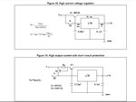
From what I know, high current (more than a little IC, a voltage regulator, or a 200mA 555 can provide) seems to come from using a transistor or MOSFET after or around the voltage providing device - the jpg with two "high current" schematics from the ST L78xx series shows a way to do that.
Hope the little I know helps. Good luck.

ST 7805 datasheet figures 13 and 14.JPG

- - - Updated - - -

And I forgot the obvious one which might be more practical for your needs: A dual polarity regulated power supply using a centre-tapped transformer... Here's a reliable looking schematic:
**broken link removed**
 

Attachments

  • 555 Application Notes 555AN.pdf
    378.7 KB · Views: 84

Re: how to make positive and negative voltage and high current

hi,
how can I make a circuit with positive and negative voltage with high current.
With such skimpy info, an informed suggestion cannot be made.
How much is "high current" and how much voltage?
Do either need to be adjustable?
Does it need to be regulated?
What is the power source?
 

Re: how to make positive and negative voltage and high current

Hi,

What is high current?

For a battery powered system even milliamperes may be high current.

Or 6000A at a power plant...


Klaus
 

Re: how to make positive and negative voltage and high current

Hi,
thank u for your answers
ok,you right
current is 200 ma
power supply is 20 volt
output voltage is -10 mv to 10 mv
also is adjustable
 

Status
Not open for further replies.

Part and Inventory Search

Welcome to EDABoard.com

Sponsor

Back
Top