TekUT
Full Member level 6
Intro
Hi all,
is now long time from writing the last tutorial on this great forum, now is time to start again with, I think, an interesting thematic about CAN bus network with PIC18F4680 microcontroller. This is a step-by-step design because I'm just starting now with this argument, the time needed to complete this project might be short or long it will depend from my spare time, my progress and the contribute from others user who may be happy to participate and cooperate together.
The idea
The idea behind this design is to connect several node each other trough the aid of a CAN bus network.
Starting from a bridge node connected to a PC we can send and receive data over the CAN network.
The purpose of this design is to overcome the limit of the classical RS232 interface in order to connect several nodes, with the aid of a CAN bus network will be more simple add others node to a existing network and a network of such type is intrinsically safe because every defective node will be automatically excluded from the network without having a negative impact on the overall operation of the network.
The last goal will be to have for each node of the network a bootloader programming feature, hence we will can easily update the nodes firmware through the network without the need to reprogramming it directly on board of the single node. With this feature we are also able to do the remote updating of the firmware inside each node without the need to reach physically the network itself.
System description
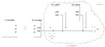
To start we can develop a simple network with two slave nodes on a breadboard adding also a bridge node used to get in communication with a PC, that will act as a master by means of the serial RS232 port, with the nodes inside the network.
In attachment you can see a simple schematic of the overall system.
Bye for now
Powermos
Hi all,
is now long time from writing the last tutorial on this great forum, now is time to start again with, I think, an interesting thematic about CAN bus network with PIC18F4680 microcontroller. This is a step-by-step design because I'm just starting now with this argument, the time needed to complete this project might be short or long it will depend from my spare time, my progress and the contribute from others user who may be happy to participate and cooperate together.
The idea
The idea behind this design is to connect several node each other trough the aid of a CAN bus network.
Starting from a bridge node connected to a PC we can send and receive data over the CAN network.
The purpose of this design is to overcome the limit of the classical RS232 interface in order to connect several nodes, with the aid of a CAN bus network will be more simple add others node to a existing network and a network of such type is intrinsically safe because every defective node will be automatically excluded from the network without having a negative impact on the overall operation of the network.
The last goal will be to have for each node of the network a bootloader programming feature, hence we will can easily update the nodes firmware through the network without the need to reprogramming it directly on board of the single node. With this feature we are also able to do the remote updating of the firmware inside each node without the need to reach physically the network itself.
System description
To start we can develop a simple network with two slave nodes on a breadboard adding also a bridge node used to get in communication with a PC, that will act as a master by means of the serial RS232 port, with the nodes inside the network.
In attachment you can see a simple schematic of the overall system.
Bye for now
Powermos