Continue to Site

Welcome to EDAboard.com

Welcome to our site! EDAboard.com is an international Electronics Discussion Forum focused on EDA software, circuits, schematics, books, theory, papers, asic, pld, 8051, DSP, Network, RF, Analog Design, PCB, Service Manuals... and a whole lot more! To participate you need to register. Registration is free. Click here to register now.

Urgent help regarding printed dipole using HFSS

Status
Not open for further replies.

kikiko

Newbie level 4
Joined
Jan 7, 2015
Messages
7
Helped
0
Reputation
0
Reaction score
0
Trophy points
1
Activity points
40
I have desigend a simple Printed dipole but i have been getting a weird rectangular plot (S11 vs freq grap) as my projected is to design Fractal antenna for wireless (2.4GHz) . What my teacher is askin me now is that thie curve should be only one and should fall on 2,4 GHz... can some body please help me and tell me why i m gtting this kindof graph!????:oops:
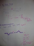
Capture.PNGCapture1.PNGDSC06818.JPG


And if somebody have designed a fractal antenna please help me to enhance this or send me the file
 
Last edited:

Your dipole has apparently a fundamental resonance (λ/2) at about 570 MHz. The order of magnitude looks plausible according to the dimensions. Review your design equations.
 

Thanks for the reply ... my supervisor suggested me to increase length from 12cm to 16 cm ...so that means i should reduce the length rite!

- - - updated - - -

So should i decrease the lenght from 16 cm to 13 cm ?
 
Last edited by a moderator:

Sir thanks for the reply ... but what do you mean by design equations .. i didnt work with any equation... just barre with me as i m a beginner

- - - Updated - - -

Your dipole is too long for 2.45GHz


this is the result of smaller dipole reduce from 16cm to 4.5cm

smaller dipole.PNG
 

my supervisor suggested me to increase length from 12cm to 16 cm

Wavelength at 2.4GHz is 12.5cm, so that the total dipole length in air would be lambda/2 = 6.25cm. Each arm is half of that length.
On substrate, it will be even shorter because the effective permittivity is larger than 1.
 
Finally after several trail and error the curve falls on 2.45GHz (Dipole one sided length is 5.9cm)

Capture.PNG
 

Ok, but what surprised me: the matching in your simulation gets better again if we look below 1.5GHz.I think this is unexpected for a dipole. Can you simulate down to 100MHz so that we see what happens there?
 

[Moved]Urgent help needed to design Koch curve

May i know how can i enhance a printed dipole(5.9cm) antenna to make a koch curve for wireless ... please help me regarding how to draw fractal like this ? do i have to divide 5.9 by 4 and then make each block ?? i m just confused


DSC06822.JPG
 

Your dipole is too long for 2.45GHz


hello sir after 2hrs of simulation this is the graph I got of printed dipole … please tell me it is rite


Gap
X: 1cm
Y: 0.5cm


Dipole
X: 0.5cm
Y: 5.8cm

5.8cm.JPG

Finaly.JPG
 

The center frequency (=length) seems to be basically correct. Don't know if your specification involves additional parameters like impedance or bandwidth.

The frequency step is a bit coarse to see the exact S11 curve. After verifying a reasonable broadband behaviour with this result, you would probably perform a simulation over a narrow range with better frequency resolution.
 

Status
Not open for further replies.

Part and Inventory Search

Welcome to EDABoard.com

Sponsor

Back
Top