Continue to Site

Welcome to EDAboard.com

Welcome to our site! EDAboard.com is an international Electronics Discussion Forum focused on EDA software, circuits, schematics, books, theory, papers, asic, pld, 8051, DSP, Network, RF, Analog Design, PCB, Service Manuals... and a whole lot more! To participate you need to register. Registration is free. Click here to register now.

Negative resistance fet oscillator, problem with transient of layout

Status
Not open for further replies.

ravch

Newbie level 5
Joined
Nov 6, 2014
Messages
10
Helped
0
Reputation
0
Reaction score
0
Trophy points
1
Activity points
75
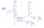
Bias: Vds = 3V, Vgs = 0.58V and Id = 60mA, Transistor: ATF541M4(avago), Frequency: 5.5 GHz
Capacitor at source port to make the transistor unstable.
bias.jpg
Using the design rules to design the negative resistance oscillator, matching networks have been created using stubs. The matching networks are tuned so that the open loop gain condition is satisfied using OscTest. HB and transient simulators are used to obtain the oscillations. The schematic is shown below. If you zoom in you can find the exact lengths of the stubs. The microstrip lengths in the source ports are very big and capacitor in source port value is increased to 10pF. This is to maintain the loop gain greater than 1 and phase close to zero.
schematic.jpg
loopgain result
loopgain.jpg
HB and tran results of the schematic are shown below.
HBresult.jpg
transient_result.jpg
Now a layout is created(layout part for the bias is incomplete) and the layout component is used to check for the oscillations.
layout.jpg
layout2.jpg
results of layout component
layout_HB_result.jpg
layout_tran_result.jpg
I tried with different values of stop time and maximum time step. But the output is still the same in transient.
I dont understand why it doesnt show the oscillations in transient even though there is harmonic result.
 
Last edited:

-Have you simulated your layout in Momentum with "RF Mode" or "Microwave Mode" ??
If you have simulated in "RF Mode", DC current will not flow because this mode does not include DC at simulation frequencies.Transmission Lines may act open circuit for DC current.
-Transient simulation may sometimes need a "trigger" to excite the circuit.This happened to me many times.
The simulator takes DC solution as a initial state and if there isn't any exiciting temporary source, transient simulation engine keeps this initial state and especially autonomous circuits like oscillators don't start up.
 

I have simulated in momentum microwave mode, not in rf mode. And also it gives the correct bias when i annotate the DC_Solution.
 
Last edited:

I have simulated in momentum microwave mode, not in rf mode. And also it gives the correct bias when i annotate the DC_Solution.

In that case, try to excite the circuit with either a current or voltage source in a temporary time slot to make the oscillator starting-up.
 

I tried to replace the ads model of lumped components with real values from murata library. I find the frequency in HB simulation as 5.375 GHz and the bias is good. But with transient, the bias is gone and frequency is 1.6 GHz.tranbias_murata.jpgtranres_murata.jpg

Like you said I tried to excite the circuit with a voltage source vtsine. I got the results as below.
tranvtsine.jpgtranvtsine2.jpgvtsine.jpg

I find there are some oscillations.
So does it mean that my circuit will work after I manufacture this layout on PCB?
Isnt it supposed to be a self oscillating? I mean a negative resistance oscillator is a circuit which gives oscillations without any input signal. But here we gave some input signal.
 

I tried to replace the ads model of lumped components with real values from murata library. I find the frequency in HB simulation as 5.375 GHz and the bias is good. But with transient, the bias is gone and frequency is 1.6 GHz.View attachment 111156View attachment 111157

Like you said I tried to excite the circuit with a voltage source vtsine. I got the results as below.
View attachment 111158View attachment 111159View attachment 111160

I find there are some oscillations.
So does it mean that my circuit will work after I manufacture this layout on PCB?
Isnt it supposed to be a self oscillating? I mean a negative resistance oscillator is a circuit which gives oscillations without any input signal. But here we gave some input signal.


Dear ravch

You excited the circuit with a sinusoidal source but it's absolutely wrong and the bias point of the transistor does not seem good.There are still some problems which are coming from DC model of the layout elements.That's why the simulations are very consistent.
You have to excite the circuit with a temporary pulse voltage/current source that will wake up the circuit at the beginning for a limited time.For instance a single shot pulse source with 10ns pulse width will-probably, try and see- wake up the circuit. We call it as "excitation the circuit" so the circuit is woken up and start to oscillate.This source may be sometimes a current single shot pulse source that is inserted into circuit at a proper point, it may also be voltage source that adds some voltage to the circuit.
It's a tricky way to trig some oscillator circuits but some circuits don't need this and they start-up very smoothly without any excitation.
If you make a zap file of your project, i can help you more..
 
  • Like
Reactions: ravch

    ravch

    Points: 2
    Helpful Answer Positive Rating
I forgot to metion..
Have you ever simulated your layout at DC ?? ( 0Hz) in Microwave mode ??
Momentum simulation frequency should be defined seperately at especially DC ( 0Hz ) because older versions of ADS ( predessor of 2014.01 ) needs a seperate DC frequency definition.You can do it for instance...

First Row of Simulation Frequency Table 0 Hz ( single point)
Second Row should be ( for instance ) 0.1GHz 10GHz
 
  • Like
Reactions: ravch

    ravch

    Points: 2
    Helpful Answer Positive Rating
The results are the same when i tried to simulate the layout in microwave mode with two different frequency plans(both enabled) as you said.

Now I tried to use vtpulse to trigger the circuit, i found the results as below.
tranvtpulse.jpgvtpulse.jpg
 

This is a .rar file in which u can find the .zap file
 

Attachments

  • oscillator541M4_wrk.rar
    8.9 MB · Views: 71

This is the .zap file of transistor atf541M4 ads model.
 

Attachments

  • atf541m4_010407.rar
    12.7 KB · Views: 74

Osc_Input.png

Dear ravch..
I think there is a fundamental error in your oscillator circuit.You have used a transistor with 2 Source pins that are practically parallel but these Source pins are connected to GND via different paths.
This will create problem because while one side is acting series feedback circuit with a series capacitor, other side has been connected to GND via a Transmission Line
It's conceptually OK since the second side TL has a lamda/4 length "exactly" that will show a open circuit for RF signals. But if its length is not so well aligned, the oscillator can create a second- maybe third- oscillation point and ti may enter into a strange bifurcation.
Why don't you try Gate Grounded configuration ?? I believe that'll work better than this.
 

(1) I understand what you said. But, I dont mind to have 2nd or 3rd harmonics. I just want my circuit to oscillate around my frequency. Since it had to be excited to wake it up, will my circuit work after manufacturing. Is it a good idea to that way.

(2)I would also like to try and design a common gate configuration osc. But i dont understand how do I bias a transistor with 4 pins in common gate config.

I don't talk about 2nd or 3rd harmonics. I talk about oscillation frequency that can be chaotic bifurcation of this configuration.I mean the oscillation frequency may not be unique..
Read a bit Grebennikov's textbook...
 

For Vds= 3 V and Ids= 60 mA, is this a good CG config?
 

Attachments

  • CGbias.jpg
    CGbias.jpg
    142 KB · Views: 90

Status
Not open for further replies.

Part and Inventory Search

Welcome to EDABoard.com

Sponsor

Back
Top