Continue to Site

Welcome to EDAboard.com

Welcome to our site! EDAboard.com is an international Electronics Discussion Forum focused on EDA software, circuits, schematics, books, theory, papers, asic, pld, 8051, DSP, Network, RF, Analog Design, PCB, Service Manuals... and a whole lot more! To participate you need to register. Registration is free. Click here to register now.

Optical Encoder diagnostic

Status
Not open for further replies.

adeleee

Newbie level 5
Joined
Dec 16, 2012
Messages
9
Helped
0
Reputation
0
Reaction score
0
Trophy points
1,281
Activity points
1,326
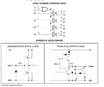
Hello every one , greetings from Egypt , I have a servo motor controlled the x-axis motion of a wide format solvent printer , yesterday , it stops suddenly and it was free to move , i replaced it by a new one and the printer worked fine , Now i want to get it working again ;) , the encoder consists of 1- IC: AM26LS31C
2- Encoder Sensor : Avago H9731
3- three SMD cap + 2 SMD res
the motor is 36V DC - 3000 RPM & Encoder : 1000P/R
the question is , how could i diagnosis the error part to replace it and get the motor run correctly again ? any suggestions could be help :)
 

sorry , could you explain ?
 

I checked the Optical Encoder Module " HEDS-9731 " , and when i tested it , i connected 5.12v to Vcc and 0v to GND , the output from Channel A and Channel B is always 5.02 v even when i close the LED path , whats the problem please ?
 

The description is not very clear, my best guess is the dc motor itself which has the problem - put some dc voltage at motor terminal, does it rotate?
 

The AM26LS31C is the most likely weak link with 5 Ohm output impedance drivers to run a motor of unknown resistance.

Best practise is to have driver ESR lower than motor ESR (winding resistance) since drivers above in spec sheet have a VI curve representing a 5 Ohm ESR and motors are generally low ESR. Motor impedance rises with commutation frequency, but start/stop surge currents can overheat the driver from I^ESR loss in driver.

Heatsink or better external FET driver may be needed to be much lower RdsOn or Rce than motor resistance to prevent stall current flying driver. Instead the motor will overheat until protection Polyfuse prevents failure. Rapid start stop can also cause this.

What is motor resistance and voltage?

I calculated 5 Ohms but TI spec
shows 6 Ohms on high side.

The IC should not dissipate more than about 1W. use Ohm'sLaw.
 

Attachments

  • image.jpg
    image.jpg
    126.8 KB · Views: 80

The description is not very clear, my best guess is the dc motor itself which has the problem - put some dc voltage at motor terminal, does it rotate?

i already tested the motor , and it runs correctly
 

the motor voltage is 36 Vdc and its resistance is 4.1 Ohms

- - - Updated - - -

i did not tested it when the motor runs , but it get hot when tested alone , i guess the encoder sensor is the problem " I checked the Optical Encoder Module " HEDS-9731 " , and when i tested it , i connected 5.12v to Vcc and 0v to GND , the output from Channel A and Channel B is always 5.02 v even when i close the LED path " , but how the photocell generate 5.02 v when it is dark ??
 

Status
Not open for further replies.

Part and Inventory Search

Welcome to EDABoard.com

Sponsor

Back
Top