Continue to Site

Welcome to EDAboard.com

Welcome to our site! EDAboard.com is an international Electronics Discussion Forum focused on EDA software, circuits, schematics, books, theory, papers, asic, pld, 8051, DSP, Network, RF, Analog Design, PCB, Service Manuals... and a whole lot more! To participate you need to register. Registration is free. Click here to register now.

bump in off time of switches

Status
Not open for further replies.

zereshki

Member level 1
Joined
Jun 15, 2008
Messages
39
Helped
1
Reputation
2
Reaction score
1
Trophy points
1,288
Activity points
1,627
hello.
I make a variable switching power supply by half bridge circuit.switches are power bjt 13007.
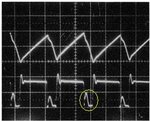
there is some bump between turning on of switches that occurs while changing duty cycle for voltage change.in some range of duty cycles this bump variate continuously change and cause make "zzzz" sound in trans and make switches warm.there is short term about it in "switching power supply-pressman" book (below picture), but not saied how to solve it.photo shows common cathode voltage of schottky rectifier of output stage.
bump.JPG

please help if any body knows about how to solve it.

regards
 

There are many factors which could be explain the problem, most of them related to circuit scope, therefore in order to get a more accurate answer essentially you also need provide the circuit diagram, preferably attaching a piece of the code responsible for the switching function.
 

In pressman book it noted that this is related to revers capacitance of rectifiers and out put L filter that make a resonance circuit. Now how to eliminate or reduce this effect? For example same as snubber that reduce resonance effect of parasitic cap and leakage inductance of trans?
 

If so is the case, you may want to use SiC diodes. They have zero reverse recovery charge and extremely small body capacitance.
https://www.digikey.com/product-sea...t=0&page=1&quantity=0&ptm=0&fid=0&pageSize=25

yes but it is end solution. how the other power supplies solved this problem, because sic diodes are not available here. I mean how to change trans layers, output LC filter values for L or C or any thing else?! :thinker:
link is not correct

regards
 

I "really love" quotes without paragraph and page information...

The first point is to understand what the figure 14.12 waveforms actually show. The picture in your post shows the "damped" case with snubbers in place. In my understanding, the author is seeing it somehow as normal operation of rectifier diodes in fast (200 kHz) power supplies. The discussion focus is on fast oscillations causing respective EMI problems, which are fairly supressed in the shown case. The said "bump" is more a regular effect of rectifier reverse recovery that can't be avoided in this circuit topology.

Your "zzzz" problems seems rather related to feedback instability. As a side effect, the rectifier and current waveforms will be continuously changing for an unstable operation point.
 
I "really love" quotes without paragraph and page information...
:roll:

The first point is to understand what the figure 14.12 waveforms actually show. The picture in your post shows the "damped" case with snubbers in place.
isn't it true that snubber effect is visible in rising edge of cathode voltage of rectifier?!

In my understanding, the author is seeing it somehow as normal operation of rectifier diodes in fast (200 kHz) power supplies. The discussion focus is on fast oscillations causing respective EMI problems, which are fairly supressed in the shown case. The said "bump" is more a regular effect of rectifier reverse recovery that can't be avoided in this circuit topology.
thanks alot

Your "zzzz" problems seems rather related to feedback instability. As a side effect, the rectifier and current waveforms will be continuously changing for an unstable operation point.
No the problem is not related to feedback instability and I designed it correctly.actually regardless of this bump the effect of instability will appear in continuously changing of duty cyclethat appear in zzzz sound. some mounts ago I had instability problem but I solved it.
in my circuit(half bridge,bjt switch,tl494 driver,60khz,0~30v,0~5A) by changing the reference voltage, duty cycle will change. by decreasing duty cycle(decreasing voltage=more off time) a damping sinusoidal wave will appear in off time of switches. it seems that the origin of this is resonance of some L and some C but which L and which C I don't know! either of output filter L,C , capacitance of rectifier, capacitance between layer wound, leakage inductance or any thing else can play a role in this problem,but I don't know which one to solve the problem.
almost (not exactly) it happen in 30% < duty cycle < 70% !!!!

regards
 

No the problem is not related to feedback instability and I designed it correctly.actually regardless of this bump the effect of instability will appear in continuously changing of duty cyclethat appear in zzzz sound. some mounts ago I had instability problem but I solved it.
You have been reporting about the "zzzz" noise, now you say it isn't there any more. That's good.

Why do you think there's still an actual problem in your design?
 
You have been reporting about the "zzzz" noise, now you say it isn't there any more. That's good.
You are right.the first time that I had this prblem( I mean screaming of trans ) I knew that the reason is instability because DC was not stable.so after some mounts of searching and study of many books finaly I design feed back loop and it worked well. It was a test circuit for check my design. After that success I decide to re design it for more out put current capability(5amper) . So I use 4 wire in parallel in secondary and re wound on same core (last time it was 2 wire in parallel) and use more current capability schotky(and of course other necessary changes). Now result is that below about 30% of DC, the damping sinusoidal wave appears and circuit start to slow zzzz and of course countinusly changing DC same as before that was instable while I use the same load.by increasing time div of scope It seems changing periode be 100 Hz. Of course rail power riple after rectifier is same!!!
So :
1- i rewound trans by same Np/Ns
2-change output rectifire
3-wave that happen in off time is damping sinusoidal
Because of that I think some factors that are in secondary side make this problem.but I don't know which one ,To solve it.
That's it.

Regards
 

Status
Not open for further replies.

Part and Inventory Search

Welcome to EDABoard.com

Sponsor

Back
Top