Continue to Site

Welcome to EDAboard.com

Welcome to our site! EDAboard.com is an international Electronics Discussion Forum focused on EDA software, circuits, schematics, books, theory, papers, asic, pld, 8051, DSP, Network, RF, Analog Design, PCB, Service Manuals... and a whole lot more! To participate you need to register. Registration is free. Click here to register now.

Simple multi-input direction circuit

Status
Not open for further replies.

Jscheel66

Newbie level 5
Joined
Aug 14, 2014
Messages
10
Helped
0
Reputation
0
Reaction score
0
Trophy points
1
Activity points
89
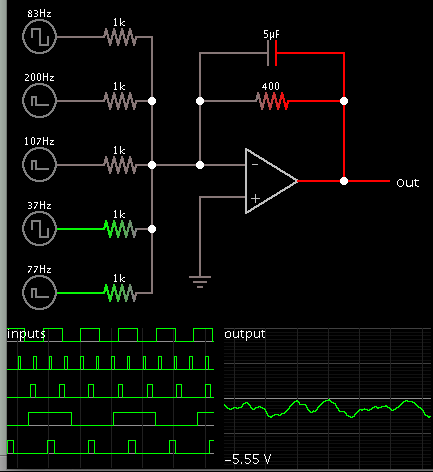
I have a question about the design of a circuit to determine direction using multiple inputs. Like 5 inputs are coming in, going high, high, low, high, high, low. Moving in a given direction to fast to see with the human eye. I think I only need 3 signal inputs to determine direction but I can have many...

I believe it should be possible to solve this with a flip flop or comparator circuit..

I need advice please. Any advice will be greatly appreciated.

Jeff
 

One possibility is a summing op amp circuit. Then add a capacitor to smooth the output.

8041764000_1408046801.png
 

Let me give a better description of the input array.
Say there is a conveyor belt running left to right in front of you. You have sensors mounted on the conveyor, along the full length. NOW: product is moving by either going right to left or left to right. It is moving way too fast for the eye to see. The sensors are being triggered in a direction also maybe there is a series of ( cans / bottles ) whatever moving is a given direction . But again too fast to see the direction. Clearly this is only a hypothetical scenario. I am working on a project which I would patent if I can get it to work. After the patent is pending I would share everything about the device.. You understand I can’t do that now. There are a lot smarter people on this site then me 

THANKS
Jeff
 

This sounds similar to a bee counter. It needs to detect the motion of bees, so that it counts bees going in one direction only.

An internet search will turn up several such projects. Example:

http://www.discovercircuits.com/H-Corner/beectr.htm

- - - Updated - - -

Sorry, on closer reading I find the discovercircuits.com project does not detect bee motion.
 

I don't understand what's the specific method you want to implement. The standard method for direction sensing uses a pair of light beams and derives the direction from the event order, either on- or off-edge at both beams. But what do you want to do with three or more sensor inputs?
 

Solution= std.quadrature detector for motion sensing , the same as a shaft encoder, except using path interuption of IR LED light. with 2 optical paths close together but separated .

Optical interruptor works well with 1 emitter and 2 detectors. ,. Each trigger would have hysteresis and would have 1 shots to prevent multiple triggers such that a valid direction signal is 2 sequential inputs where the 1st must be blocked while the 2nd gets blocked and the 1st must be cleared before the 2nd.

Thus the 2 detectors are side by side and detect direction and must be closer than the bee body length. Optics must be blocked in all directions except an aperture of slotted or straw-piped line of site across the tube thus 2 narrow angle IR detects with daylight blocking should work fine with 1 emitter.

The pulse width can be very narrow and interval faster than the bee speed. IRDA pairs work well or discrete IR Sharp/Vishay parts work well with deep black heat shrink apertures for pinpoint detection.

BTW , this is the same method, used by rotary encoders using quadrature sensing with two detectors.


Any questions?


I've used this method using PIC uC before. For bonus points you can monitor average wing flap frequency and hive temp to detect when a new Queen is born. ( friend in NZ did this 8 yrs ago with remote sensors and mic with spectral analysis on PC.
 

OK... now were getting somewhere.. FIRST THANKS FOR YOUR GUYS HELP. Let me look at the Bee circuit design and I will post after...

Jeff
 

The Bee counter will have lots of false counts from fringe effects.

You need 2 detectors get get accurate direction and counts using a Finite State Machine simple decoder in software or using flip flops and gates to ensure no false counts. ( standard quadrature counter method)...

Trust me , you need more than what was given on link for photo-interrupter.
 

I am afraid a bee counter is not going to give me direction or if I does I don't understand how.. I am trying to determine direction something is moving by looking at only sensor inputs. These inputs if slowed down would look like a wave or series of waves moving from one side to the other, but considering it is moving so fast one can not visually distinguish direction.

- - - Updated - - -

can you tell me more about the standard quadrature counter method and how I would use gates and flip flops to determine direction. I do believe gates and flip flops is the right way to go.. Please give me more advice..

- - - Updated - - -

Imagine these inputs are being triggered like a wave moves and many waves, but all going in the same direction. How would I use a circuit or flip flops to determine direction?
Jeff
 

The quadrature detector consists of;:arrow: 2 inputs and 2 outputs .
"perfection, depends on how you define the specs with details, for error free- performance, as in noisy data streams BER, here is the BEE ERROR RATE." nothing simple is perfect!:roll::roll::!:

Let's call inputs A & B valid when both are blocked "1" then unblocked "0" to detect one bee going through by choosing a threshold of light and then using hysteresis around this threshold such as a comparator with positive feedback or a Schmitt trigger.

Filtering of the edge of a bee through an infrared transmission block can be done with analog continuous light and LPF analog noise filters with hysteresis or pulsed light and a digital filter , gating(And) consecutive states to be the same. This must be designed to reject false noise counts and only detect true bee body counts and not wing flaps.

Pulsed-IR hasthe advantageof higher SNR at lower average power. IR with daylight blocking fliter on the Detector gives better SNR. Narrowtunnel apertures for emitter/detector path gives more SNR from blocking stray paths (multipath distortion) e.g.5mm parts with black heat shrink over them will give higher pulse SNR & better signal level stability to give more precise threshold detection at 25 to 50% of average peak level so thatAGC is not required.

:arrow:
The output is either Direction and Count pulse or Count up & Count Down is determined by the which edge is detected first.

Validation or filtering improves detection when the bee goes past the two quadrature detectors in the same direction, mean both go "1" then "0" in the same sequence, otherwise the pulse is rejected as noise.

There are literally hundreds of different implementations of the above rules, where the tradeoff is often false & missed count error rate vs complexity or technique of digital filtering noise, so there are can be simple effective ways and also exotic single chip solutions that measure direction and speed.

Let me see if you understand so far and browse these possible flip flop https://www.google.com/search?tbm=i...wn quadrature decoder count&tbm=isch&imgdii=_methods

It can also be done with one shots and gates with feedback .
**broken link removed**
 

THANK YOU Sunnyskyguy :) and everyone else.....
I have been all over those circuits. I fear using only 2 inputs where 1 must be triggered first for the direction will not work. My sensor array is being built now. HA HA on my kitchen table. It's going to have 10 sensors I can not say what kind ( sorry it is my intention to patent this device once working. ) I will tell all after the patent in pending.. And at this early point I am grateful for your help. Just so you know... :)

Think of the inputs being triggered like a wave or many waves going in one direction and not necessarily being triggered starting with the first channel in the array.. Like someone waving there hand over a row of light sensors. Moving from right to left or left to right. Maybe locking or unlocking a door. The triggers will be tripped in a certain direction but not always tripping the first one first...

Please let me know what you think...

Jeff
 

please look at this circuit and let me know if you think it will work?..

CircuitDiagram1.png

Jeff
 
Last edited by a moderator:

No. This is gives a gain of 1,2,or3 on a logic level that could contain errors, noise pulses false signal. NG. Now if it were shifted values in time, you get a digital low pass filter. From spacial receivers you increase selectivity, but that isn't enough.

But if you start with some specs for BEE Error Rate on false +'s and false -'s like 1 in 10^4 BER, then we can start with the method of analog detection, level of signal/noise ratio then quadrature discrimination method, we can start designing... Not before.

Forget about patents and microphones until you have written a test and acceptance criteria for the design. :grin:

Define bee aperture size to hive and bee physical characteristics and possibility of multiple Bees in either direction near sensor.

Get my drift? Then we can talk , optical, acoustic etc then transmission, reflection, then variation levels, stray noise. Then panic modes with smoke and traffic jams. Etc. all in your spec.
 

No I don't really get what your saying.. Pretend you know much more about electronic then I do. And this has nothing to do with counting... I want to determine which way the wave is going... I think 3 inputs is all that needed to show which way something is going... I will buy you a beer if you help me design this... What about a gift certificate to Terra 8199 Yonge St, Thornhill, OR Marlowe Restaurant 155 York Blvd #1, Richmond Hill, .. :)

Jeff
 

Pretend you see what you want this to do and describe what it looks like and how the Bees are moving thru the chamber where you would like to count flow, so I can see if it is practical.

I can translate any detail oriented physical requirement into an electronic design, but so far you missing a lot of physical details. It is much more complex than you imagine, so be specific after you understand what innovation you need.

The description does not need to be complex if you have pictures, but some scope as to the size of the project, DIY or do you have a demand for such a product already?

Start here. https://www.google.ca/search?q=hive+bee+counter&ie=utf-8&oe=utf-8&aq=t&rls=org.mozilla:en-US:eek:fficial&client=firefox-a&channel=sb&gfe_rd=cr&ei=Xxf2U_jPOe3L8gf4sYHYDw


I can not talk about the sensor array, but to say it is a row of sensors. I can make them go high or low when triggered. Imagine a row of sensors and a ball rolling across them tripping them 1, 2 or 3 at a time. The ball is rolling from right to the left or the other way. I need to take the signals coming off the array and interpret the signals into a direction. QUESTION " did the ball roll from left to right or right to left.. ??
Like at this like a block diagram. only 3 inputs A, B, C ... the ball rolls from right to left. the ball trips A then B. When B is tripped it switches on A and C now were waiting for the ball to trip either A or C . If C trips next the ball was going to the right if A trips next the ball was going to left. When C is tripped the circuit says RIGHT and gives a momentary output right then resets it's self to run again...

Follow me?

Jeff
 

I made a typo about the balls direction.. It is corrected is this paragraph...

I can not talk about the sensor array, but to say it is a row of sensors. I can make them go high or low when triggered. Imagine a row of sensors and a ball rolling across them tripping them 1, 2 or 3 at a time. The ball is rolling from right to the left or the other way. I need to take the signals coming off the array and interpret the signals into a direction. QUESTION " did the ball roll from left to right or right to left.. ??
Like at this like a block diagram. only 3 inputs A, B, C ... the ball rolls from left to right. the ball trips A then B. When B is tripped it switches on A and C now were waiting for the ball to trip either A or C . If C trips next the ball was going to the right if A trips next the ball was going to left. When C is tripped the circuit says RIGHT and gives a momentary output right then resets it's self to run again...

Follow me?

Jeff
 

Status
Not open for further replies.

Part and Inventory Search

Welcome to EDABoard.com

Sponsor

Back
Top