Continue to Site

Welcome to EDAboard.com

Welcome to our site! EDAboard.com is an international Electronics Discussion Forum focused on EDA software, circuits, schematics, books, theory, papers, asic, pld, 8051, DSP, Network, RF, Analog Design, PCB, Service Manuals... and a whole lot more! To participate you need to register. Registration is free. Click here to register now.

Can someone help me complete this circuit?

Status
Not open for further replies.

Resistanceisfutile

Member level 4
Joined
Aug 22, 2012
Messages
77
Helped
2
Reputation
4
Reaction score
1
Trophy points
1,288
Activity points
2,008
The schematic below is a drawing of a radio controlled car (the controller) circuit. The drawing is a copy of the circuit board. The big gap in the centre (with a ?) was concealed by a blob of something that I can't remove. The number of wires going into this area is even so I'm assuming each wire connects only to another one.
Can anyone see which wire would connect to what?
Also, the tuned circuit at the top right has a resonant frequency of 1.25 Petahertz, I'm guessing this can't be right?

If you can't solve any of these questions (or if you can), feel free to have the circuit for your own use. It works and is one of the few I've seen that doesn't contain an IC.
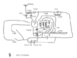
RadioControlledCarCircuit.png
 

The big gap in the centre (with a ?) was concealed by a blob of something that I can't remove. The number of wires going into this area is even so I'm assuming each wire connects only to another one. It works and is one of the few I've seen that doesn't contain an IC.

It's most likely a die wire bonded to the PCB, so it's encapsulated with some non-conductive resin to keep it protected. The receiver/controller is buried under that blob, so yes this board also contains an IC you just don't have a package on the board.

Regards
 

NOOOOOOOOOOOOOOOOOOOOOOOOOOOOOOOOOOOOO :(!
Ok, thank you for telling me.
 

Thanks, I'll check that out.
Hopefully I'm not necrobumping, but I just wondered: why do remote controls need an IC to operate?
 

Hopefully I'm not necrobumping, but I just wondered: why do remote controls need an IC to operate?
No, it's a reasonable question I think.

The RC in the link uses popular encoder/decoder ICs to transmit multiple commands through a single RF channel. It's a kind of pulse modulation where different command are encoded as specific pulse patterns. Your chip-on-board transmitter does probably the same.

A remote control using only transistors would probably refer to different modulation methods, e.g. multi frequency tones.
 

I'm guessing this wouldn't be liked in a commercially sold model because it would be a little channel greedy but, could someone simply design their transmitter to operate on four frequencies (if there are four functions) without the need for an IC?
 

I'm guessing this wouldn't be liked in a commercially sold model because it would be a little channel greedy but, could someone simply design their transmitter to operate on four frequencies (if there are four functions) without the need for an IC?
Well yeah it could be done, but then the big mean bully next door will beat up you up when his helicopter crashes when you turn on your multi-channel transmitter, that has one channel that is shared with his transmitter.

Both sets of bands for RC usage are pretty crowded already and many of the RC units have easily swapable crystals to allow for quick frequency changes so you aren't stomping on another's signal. The standard protocol in areas where RC modelers congregate is to turn on your receiver and see if it responds to any signal before turning on your transmitter. People tend to get upset when their plane crashes or when they loose control of it and it "attacks" bystanders.
 

Apart from other issues, using four different RF carrier frequencies means you need either four separate receivers or a frequency scanning receiver. No good idea, I think.
 

Good point cost is a definite factor in having four RF carriers as you need four of everything and then having to deal with having to replace something like this **broken link removed** when you cause it to crash after turning on your four RF carrier transmitter.
 

I think the very cheap and old circuit for the radio controlled car is extremely simple and is called "bang-bang" because it is FULL left turning, center or FULL right turning and FULL speed or stopped.

My modern radio controlled model airplanes use fully proportional controls: any amount of turning, banking, climbing, diving, speed control and flaps control. The 6th channel can be used to drop an object or retract the wheels. All the controls can be used at the same time.
It operates at 2.4GHz with spread spectrum frequencies and it automatically selects an unused pair of frequencies. A model and transmitter are "binded" together with a unique code so that no other transmitter can affect the controls of the model. The manufacturer operated 100 systems at the same time for extended periods and no interference was detected. The newer systems have telemetry where the receiver sends information about battery voltage, speed and altitude back to the transmitter screen. Model cars and boats are also controlled with this system.
 

I checked some of the new systems out and they are pretty impressive compared to those ancient analog RC units I used when I was into the hobby.
 

Status
Not open for further replies.

Part and Inventory Search

Welcome to EDABoard.com

Sponsor

Back
Top