Continue to Site

Welcome to EDAboard.com

Welcome to our site! EDAboard.com is an international Electronics Discussion Forum focused on EDA software, circuits, schematics, books, theory, papers, asic, pld, 8051, DSP, Network, RF, Analog Design, PCB, Service Manuals... and a whole lot more! To participate you need to register. Registration is free. Click here to register now.

Solar inverter driver issue

Status
Not open for further replies.

mathespbe

Full Member level 3
Joined
Jul 10, 2013
Messages
185
Helped
45
Reputation
90
Reaction score
44
Trophy points
28
Location
India, Tamilnadu, Coimbatore
Activity points
866
Hi experts...
Warm regards to u all...

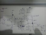
I have designed a solar inverter with IR2110 driver. I have attached the schematic for one section of high side. When i check the pulses across the gate and emitters of each IGBT is proper. When I give 315V DC to my H bridge, One of the high side and opposite low side IGBTs get damaged. Can anyone guess the issue. I'm getting stuck with this serious issue.
 

Attachments

  • 2014-08-11 17.46.34.jpg
    2014-08-11 17.46.34.jpg
    984.4 KB · Views: 129

I suspect you've got some dangerous ringing during IGBT switching.. dou you have an output filter and some good 315V DC bus capacitors (low RDS, high pulse capability)?
 

I am using the same 315V DC to my SMPS which outputs 3.3v and 24v supplies. It runs with out any issues. It's just a full wave rectifier with 4700uF/450v filter caps. And also a capacitor bank comprises of 20x470uf/1000v caps.
 

Don't you have a scope to look up for some output waveforms? Are your IGBTs rated for your application? The reason for blowing up your cross connected IGBTs might be an overcurrent (usually, at full load) or some voltage spikes (ringing) due to incorrect output filter design (resonant circuit). Also, a slow turn off could lead your IGBTs to work on the linear region so they could reach the maximum power dissipation level (I recommend using a reverse polarised fast switching diode betwen driver output and IGBT gate for a fast turn-off).

Do they run hot before they're blowing up or this happens suddenly, once you connect the power? Does it happening at no load/full load?

hi,
my igbts are upto my rating. its 650v/40amps rated.
i checked the driver output waveforms at the gate without power supply to the igbt. it was in the specified sequence as i am expecting. it was initially worked upto 2200 watts load. i turned off it and when restart it after half an hour, it was blown up. after that it doesn't responds even at 200w lamp load...

as per my operation, 315v dc available for my igbts at all the time. aftr 10 sec gate signals were given. immediately when the driver signals given to the igbt, it gets blown up. no more over heating. suddenly it get shorted.

i'm having some clueless questions. why should it work for 2200w load. after restarting why did it blown up regardless of load??
 
Last edited:

I guess my issue might be as follows.

There may be some rise time and fall time in the IR2110 which doesn't match with the sequence of the opposite IGBTs. It wasn't detected when i check the signals without supply to H-BRIDGE.
I suspect that when the IGBT is powered, the rise time and fall time plays horribly?

Pls someone correct me if i'm wrong...

I can't check the signals at gate when the IGBTs are given the power supply. am I right?

Then how could I verify and solve this issue?
 

What's your switching frequency? Is it comparable to rise time/fall time of IR2110 or IGBTs turn on/off?

I was talking about H-bridge output waveform.. does it have any ringing or something?
 

My swithing frequency for high side is 18KHz. For low side 50Hz square wave. IGBT is getting shorted at the moment of supply and gate signal is available. No ringings or spikes present in my input 315v DC.
 

Do you have reverse polarised diodes across each IGBT (collector - emitter)? That's for reverse current path, when IGBT is switched off.

Do you have a complete schematic of the H-bridge (including the output filter)? What kind of load do you have (inductive/resistive)?

I suggest to start with a small (resistive) load and a fuse on the DC bus then check the waveforms. Then you could switch to a (small, at first) inductive load and do some measurements again.
 

Status
Not open for further replies.

Similar threads

Part and Inventory Search

Welcome to EDABoard.com

Sponsor

Back
Top