Continue to Site

Welcome to EDAboard.com

Welcome to our site! EDAboard.com is an international Electronics Discussion Forum focused on EDA software, circuits, schematics, books, theory, papers, asic, pld, 8051, DSP, Network, RF, Analog Design, PCB, Service Manuals... and a whole lot more! To participate you need to register. Registration is free. Click here to register now.

[SOLVED] defective GENIUS 40 W Powered speakers

Status
Not open for further replies.

flolan

Newbie level 4
Joined
Mar 10, 2014
Messages
6
Helped
0
Reputation
0
Reaction score
0
Trophy points
1
Location
France
Activity points
62
Hello everyone,
only one speaker works correctly, the other one the sound is subdued.
may this be caused by bad capacitor ? :?:

(my mistake is to have left those speakers turned on 24/24 more than two years, it's heating and there is no ventilation)
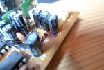
 

Powered speaker suggests it has an internal amplifier. Any number of problems could develop, to cause faulty sound.

Capacitors are among the first components to suspect, especially if it is an electrolytic type in older equipment, and if temperatures have been high.
 

hi Brad,
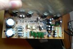
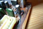
on the pictures I can see black stuff leaking around the capacitor, but I think it's glue because it's thick and hard...but there's a lot and it's not normal.
on another picture it's more redish, but I suspect it's glue too.
and with all that glue it's hard to tell if there is any leakeage of electrolyte.
No bulging capacitor.

How can I test those 4 TDA screwed on the heatsink ?
if one of them is dead, will it have the same temperature than the other ones when I turn on the speakers ?
May I spot a bad TDA this way (with an infrared thermometer for example) ?
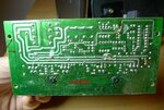
P1020509 (Large).JPGP1020513 (Large).JPGP1020504 (Large).JPG
 

It's very difficult to tell a bad IC from a good one from the outside. The temperature may or may not be different so you can use that as a diagnosis method. However, when those devices die it is usually catastrophic, you see a hole blown right through the plastic. It's more likely one of the smaller capacitors has gone open circuit, especially after prolonged use at high temperature. Even from new and at low temperature they only have a life expectancy of around 8,000 hours (about one year) before going out of specification. Note that 'out of specificaion' doesn't mean the circuit fails, just that it's value may be out of marked tolerance.

The black stuff looks like thick glue, it was used quite often as a super cheap way of making it vibration proof so the larger components didn't wobble and tear their solder joints. It was quite important in loudspeakers where vibrations would obviously be present. I have seen it become conductive as it gets older but it's rare and you can easily check it by placing Ohmmeter probes close together in it and seeing if there is a measurable resistance. Ideally there shouldn't be.

Brian.
 
  • Like
Reactions: flolan

    flolan

    Points: 2
    Helpful Answer Positive Rating
An oscilloscope is invaluable for diagnosing these problems.

* Check the power supply for proper volt level.

* Check volt output across the speakers. It should not have a DC component (whether soft or loud).

* A mosfet/transistor/IC whose innards are fused will run hot, using overmuch power, diverting it from other components. Sound quality and loudness will suffer.

* If a component has gone open circuit, then it will run cool. But it might also run cool if some other component has gone open circuit.

* Use a magnifying glass to search for cracks in solder joints, board traces, etc.

* Press your finger against two mosfets/transistors which are identical (or mounted in symmetrical positions), to see if one is running hot.

* Do you have two identical powered speakers? One thing you can try is to compare volt levels at various locations.
 
  • Like
Reactions: flolan

    flolan

    Points: 2
    Helpful Answer Positive Rating
yes, both speakers are identical 2x30W (not 40W)

power on:
all TDA have the same temperature, no suspected heat or coolness after 15 min.
volts level at various electrolytic type capacitors, I read on multimeter:

•20V not decreasing (for 100 uF/25V) and for the 2 big capacitors (4700 uF/25V)
•5V not decreasing (for another 100 uF/25V)
•beetween 3mV and 5mV, and others -0,4mV (checked with correct polarity) not decreasing
•and around 10mV quickly decreasing (for several 4,7 uF/50V, especially the "redish leak" one )

in the defective speaker the sound is good, no strange noise, it's just the loudness that has only 30 % left I would say (there is no balance control on those speakers)

now I remember that before ever noticing this problem of subdued speaker, I had strong noise when touching loudness button, and now no more noise at all ??
as if something was going wrong gradually, then broke.

P1020511redDRAW.jpg
 
Last edited:

in the defective speaker the sound is good, no strange noise, it's just the loudness that has only 30 % left I would say (there is no balance control on those speakers)

This suggests the output transistors/mosfets need greater signal bias.

Since audio quality is good, they probably have sufficient DC bias. They are in a good operating range.

And their response appears balanced, because distortion results if one goes bad, partially or totally.

Distortion results if the power supply is anemic, or if smoothing capacitors are bad.

Regarding how much signal bias gets through... There are many places where it can be attenuated. Many components you will need to check.

Your photograph shows solder repairs. Did nearby components get overheated from these repairs?

Your red arrow points to a wire which is not quite soldered in, but looks as though it needs more solder around it. What is the story on that?

Here is an effective test to try. Can you apply an external audio signal to the bias of the output mosfets/transistors? This will test whether they still amplify sufficiently.

It is a delicate operation however. You should put a potentiometer and capacitor in series with the external signal. You must not allow overmuch current draw (in either direction).
 
  • Like
Reactions: flolan

    flolan

    Points: 2
    Helpful Answer Positive Rating
This suggests the output transistors/mosfets need greater signal bias.

Brad, I would guess (can you confirm the number on them please flolan) they are TDA2030 ICs so all the bias networks are internal to the device. My guess is the capacitor across the negative feedback path is open circuit and the extra feedback has cause a drop in gain.

Brian.
 
  • Like
Reactions: flolan

    flolan

    Points: 2
    Helpful Answer Positive Rating
I bought those speakers new on a website, but may have gotten refurbished ones. I did no solder repair on it yet (just tried to clean a bit), maybe someone did without me knowing.

the wire which is not quite soldered in relates to a capacitor (read on multimeter 5V not decreasing, spec. 100 uF/25V) photo below. It seems it holds onto the board, but surely needs resoldering.

Yes Brian, those TDA are 2030A
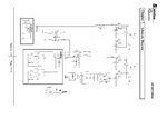
can you show me on the photograph which capacitor(s) you're talking about ? I join the shematic diagram if it helps.

I've found that the 2 TDA related to the defective speaker are on the right of the heatsink. I know because when I rub my thumb on their pins I hear some noise on that speaker.
Regarding the diagram I don't know if the defective speaker is the "Right" or the "Left" one, but when I face it it's on my left side, and it's the one with the amplifier part inside.
montage.jpgSP_HF2000A service manual_Page_16.jpg
 

Wow, you have a schematic, I'm impressed. Usually when something like this comes my way I spend hours trying to trace it out by hand.

This makes thing VERY much easier. The first thing to do is plug headphones in and see it the volume is also lower through them. The headphone socket is connected after the first stage of amplification and the volume/tone controls but before the main power amplifier. If you can establish whether the problem is in the pre-amp or the main amp it divides the problem in half.

If the fault is also obvious through the 'phones I would suggest that either C15 & C21 *OR* C16 & C22 are prime suspects.
If the phones sound OK and the low volume is only through the loudspeaker I would suggest it is C2 & C5 *OR* C9 & C12.
I give the 'OR' alternatives because of the doubt over which channel is which. Your thumb trick might help to decide that.

To be perfectly honest, the cost of capacitors is fairly low and they do degenerate over time anyway so it might be easiest to change them all in one go. The fault could lie elsewhere but those would be my first best guesses. I would need to look at signals with an oscilloscope to make a more accurate diagnosis.

Brian.
 
  • Like
Reactions: flolan

    flolan

    Points: 2
    Helpful Answer Positive Rating
the headphones sound is OK in both speakers.

I will order all the small capacitors (not the 2 big ones), and first try to change C2/C5 because they are clearly related to the TDA's defective speaker.

I need several 22uf/25V but on my electronic parts webshop they have only 22uf/50V in regular 105° cap, except in low ESR they have the correct spec. 22uf/25V.
which one should I choose, is it OK to use low ESR in this case or should I go with the regular ones despite higher voltage?

I want to thank you both for your kindness, excellent help and learning opportunity !

(I will post the result of repairing in 8-10 days)
 
Last edited:

Low ESR is better but in that applicaton it is almost irrelevant because the difference between high and low ESR is only one or two ohms and it has a 1000 Ohms resistor in series with it anyway. Generally, keep to the same capacitance (uF) but anything with the same or higher voltage rating is suitable. The temperature rating is also of very little importance, standard parts are rated to 85C and high temperature parts to 105C but the chances of the ever reaching even 85C are very slim in an amplifier situation.

Brian.
 
  • Like
Reactions: flolan

    flolan

    Points: 2
    Helpful Answer Positive Rating
repair is done:

I changed C2/C5 and strangly enough this reversed the problem; defective speaker became good and the former good one became subdued.
maybe because the new caps were slightly different in voltage (old: 25V, new: 50V)
so I changed C9/C12 and this time sound was good and balanced in both channel !
then I changed all the small capacitors to start anew with these speakers.

the sound is very good now, I'm happy.
thank you both again for helping me out with my first repair of an electronic device.

Flo
 

You are welcome. Well done!

Quite likely both channels were suffering and when you changed the bad capacitors that channel then worked better than the 'good' one. The voltage rating has nothing to do with it but anything higher than before will work equally well.

Brian.
 

Congratulations! This triumph gives you that much more confidence that you can be in charge of your environment. You need not be at the mercy of the system.
 

Status
Not open for further replies.

Part and Inventory Search

Welcome to EDABoard.com

Sponsor

Back
Top