Continue to Site

Welcome to EDAboard.com

Welcome to our site! EDAboard.com is an international Electronics Discussion Forum focused on EDA software, circuits, schematics, books, theory, papers, asic, pld, 8051, DSP, Network, RF, Analog Design, PCB, Service Manuals... and a whole lot more! To participate you need to register. Registration is free. Click here to register now.

Resistors in amplifier circuit?

Status
Not open for further replies.

Parv Kumar Choudhary

Newbie level 1
Joined
Oct 23, 2013
Messages
1
Helped
0
Reputation
0
Reaction score
0
Trophy points
1
Activity points
9
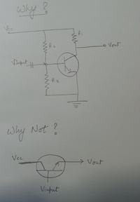
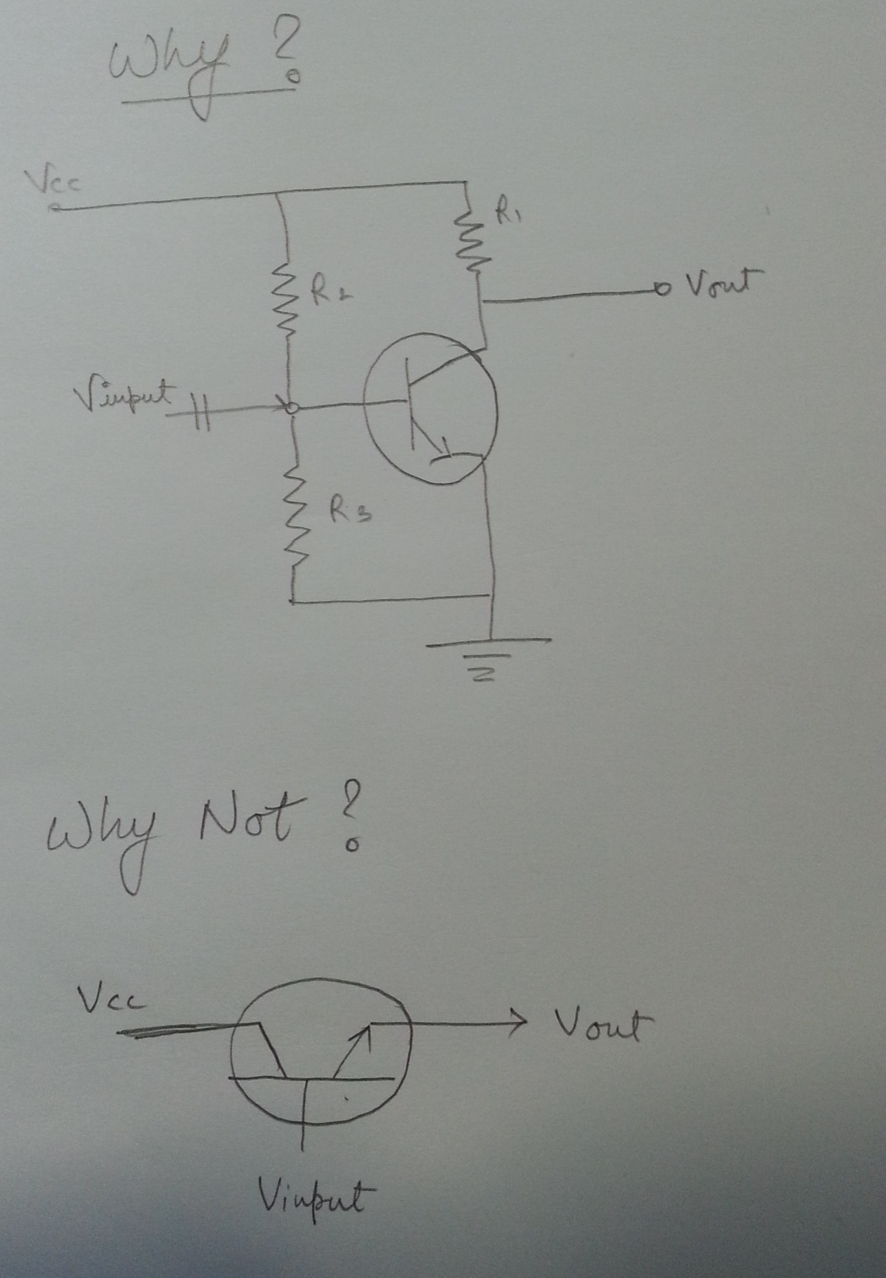
So I am learning basic amplifiers i.e. using transistors. But I don't really get the point of using resistors in the circuit. Why can't we just just put the input at the base, output at the emitter, and the required amplification at the collector?


I hope you can understand that it is not possible to explain the working principle of a BJT in this forum.
Please, consult any textbook or any other source of information.
Thus, only one basic information: The BJT is a device that needs a dc current between Cand E. This enables a so called "bias point" around which amplification can take place.It is the purpose of the dc voltage source and the several resistances to establish this bias point.
 

If your extremely simple unbiased transistor has its base biased by 2 resistors and has a resistor from its emitter to ground then it will be an "emitter-follower" that has no voltage gain (no amplification because its output voltage swing is the same or a little less than the input voltage swing). But it has a high input impedance and a fairly low output impedance.
 

@ Parv Kumar Choudhary

same as your car needs fuel to run... transistor too needs something to amplify your data!!! and it won't do that for free but on the cost of DC supply for which resistor is being used.... rest is all there in your text book !

Cheers
 

Status
Not open for further replies.

Part and Inventory Search

Welcome to EDABoard.com

Sponsor

Back
Top