Continue to Site

Welcome to EDAboard.com

Welcome to our site! EDAboard.com is an international Electronics Discussion Forum focused on EDA software, circuits, schematics, books, theory, papers, asic, pld, 8051, DSP, Network, RF, Analog Design, PCB, Service Manuals... and a whole lot more! To participate you need to register. Registration is free. Click here to register now.

Heater controlled by a PIC16F877A interfaced to a triac

Status
Not open for further replies.

jean12

Advanced Member level 2
Joined
Aug 27, 2013
Messages
529
Helped
5
Reputation
12
Reaction score
6
Trophy points
18
Activity points
5,497
Hello there,can you please help me to control a triac in ccs c for powering a heater resistances and control its temperature.
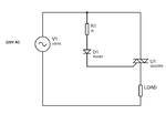
For temperature reading there is no problem but with TRIAC control with zero crossing,this is a great for me ,can you please help me to do that in ccs c;Tahmid has didi in MikroC but I don't know how to use MikroC,https://tahmidmc.blogspot.com/2013/06/ac-power-control-with-thyristor-pulse.html and https://tahmidmc.blogspot.com/2013/07/ac-power-control-with-thyristor.html

Please help.

Thanks.
 

first of all you should detect zero cross of your line power, show you a circuit although you can fine ICs over the net ( such as HT46R47 )
secondly for controlling the heater find and optotriac ( MOC3052 is my recommendation. don't choose an optotriac with zerocross).

finally after detecting the zero cross you are able to control the fire triac and trigger time.

I am using PIC16F877A and I want to detect the zero crossing with it.
Any idea on programming this?

Thanks.
 

In this link https://tahmidmc.blogspot.in/2013/06/ac-power-control-with-thyristor-pulse.html

When ever there is a zero crossing INT0 will detect it and ZC is made high.

TRIAC conducts in both direction. If you want to reduce power to 50% then you have to fire triac for 90 degrees in each half cycle of AC. Trigger TRIAC at Zero crossing. Freq = 50 Hz (AC).
T = 0.2 sec.

90 degree of half cycle is 0.005 sec = 50 ms.

Fire triac for 50 ms when ever there is a zero crossing.

t = 0, triac fires for 50 ms, 50% of half cycle is conducted. Next 50% is not conducted. Then another ZC occurs and conducts negative half cycles' 50% and repeats.
 
Last edited:

In this link https://tahmidmc.blogspot.in/2013/06/ac-power-control-with-thyristor-pulse.html

When ever there is a zero crossing INT0 will detect it and ZC is made high.

TRIAC conducts in both direction. If you want to reduce power to 50% then you have to fire triac for 90 degrees in each half cycle of AC. Trigger TRIAC at Zero crossing. Freq = 50 Hz (AC).
T = 0.2 sec.

90 degree of half cycle is 0.005 sec = 50 ms.

Fire triac for 50 ms when ever there is a zero crossing.

t = 0, triac fires for 50 ms, 50% of haff cycle is conducted. Next 50% is not conducted. Then another ZC occurs and conducts negative half cycles' 50% and repeats.

I want to change the delay angle which determines how long to fire the TRIAC with a variable resistors connected to an PIC Pin where it can operates perfectly,can you guide me?

Thanks.
 

the best way to do that is using timer. after the interrupt you should run your timer ( use in the PWM mode ).
 

Its very easy. First find the zero crossing signal. Then using TMR0(PIC MCU) generate a gate firing pulse. make a variable delay in this pulse with zero crossing signal to control the output phase angle. Measure the temperature, compare with the set value. change the FA as required. I've recently **broken link removed**.
 

Hello there,can you help me to collect those codes now for getting the good values?
PHP:
#include"16f877a.h"
#device adc=10
#fuses HS,NOWDT,NOLVP,NODEBUG,NOCPD
#use delay(clock=4M)
#int_ext


int value,delaya;
unsigned long value1;
unsigned int value2;

void isrext()
{

output_D(0xff);
delay_ms(1000);

}


void main() 
{
set_tris_a(0xff);
set_tris_b(0x01);
set_tris_d(0x00);

setup_comparator(NC_NC_NC_NC);
setup_adc(ADC_CLOCK_INTERNAL);
setup_adc_ports(AN0);
set_adc_channel(0);
setup_vref(False);


int x=0;
enable_interrupts(int_ext);
enable_interrupts(global);
ext_int_edge(L_TO_H);
while(1)

{
delay_us(20);
read_adc(adc_start_only);
delay_us(20);
value=read_adc(adc_read_only);
value1=(value*500)/1023;
value2=value1;
delaya=(value2*20)/5;

output_high(PIN_D0);
delay_ms(delaya);
output_low(PIN_D0);
}
}
I supposed that the variable resistor maximum voltage is 5V and then when  it ia being adjusted 0V..........5V
we will be having a delay of :(20ms/value of voltage on resistors)/5V
 

Why don't you zip and post your CCS C project files and Proteus file. Why do you expect others to Create a project and test your code and Simulation?
 

Why don't you zip and post your CCS C project files and Proteus file. Why do you expect others to Create a project and test your code and Simulation?

Hello jayanth.devarayanadurga here are the circuit in but it is nor running,the codes also are here:
PHP:
#include"16f877a.h"
#device adc=10
#fuses HS,NOWDT,NOLVP,NODEBUG,NOCPD
#use delay(clock=4M)
#int_ext


int value,delaya;
unsigned long value1;
unsigned int value2;

void isrext()
{

output_c(0xff);
delay_ms(1000);

}


void main() 
{
set_tris_a(0xff);
set_tris_b(0x01);
set_tris_c(0x00);

setup_comparator(NC_NC_NC_NC);
setup_adc(ADC_CLOCK_INTERNAL);
setup_adc_ports(AN0);
set_adc_channel(0);
setup_vref(False);


int x=0;
enable_interrupts(int_ext);
enable_interrupts(global);
ext_int_edge(L_TO_H);
while(1)

{
delay_us(20);
read_adc(adc_start_only);
delay_us(20);
value=read_adc(adc_read_only);
value1=(value*500)/1023;
value2=value1;
delaya=(value2*20)/5;

output_high(PIN_c6);
delay_ms(delaya);
output_low(PIN_c6);
}
}

Thanks;I made this circuit on the board also it is not working but when simulating I am only getting the variation of delay angle which was supposed to trigger the TRIAC.

Thanks
 

Attachments

  • TRRIAC.zip
    22.7 KB · Views: 51

Post your CCS C project files zipped. You just posted the Proteus file.

Hello,jayanth.devarayanadurga here are the files for my CCS C project.

I want to control the bulb from 0V to 220V.

Thanks

Thanks for helping.
 

Attachments

  • CCS FILEE.zip
    17.2 KB · Views: 52

Hello jayanth.devarayanadurga,can you help me to think on how I can drive the Seven Segment Display with portB of PIC16F877A but using RB0 as Zero -Cross detection.
I want the SSD to ve driven by the pin RB1-RB7 and then use RB0 for interrupts to sense the zero cross signal from AC source; I am design a digital thermostat where I have to display the temperature from the heater resistance and the thermostat be controlled via a TRIAC.
see the codes below:
PHP:
#include"16f877a.h"
#device adc=10
#fuses HS,NOWDT,NOLVP,NODEBUG,NOCPD
#use delay(clock=4M)
#int_ext

//--------------START of variable for Pulse delay definition---------------
int valuet;
unsigned long value1;
unsigned int value3,delaya;

//--------------Ends of variable for Pulse delay definition---------------

//--------------START OF variable for temperature reading---------------
byte const digit[]={0xC0,0xF9,0xA4,0xB0,0x99,0x92,0x82,0xF8,0x80,0x90}; //Changed this as there was error in the previous one

char display[2];
int value;
unsigned long volt;
unsigned int value2;
//--------------END  OF variable for temperature reading---------------

void isrext()
{
output_c(0xff);
delay_ms(1000);
}

void main() 
{
set_tris_a(0xff);
set_tris_b(0x01);
set_tris_c(0x00);
set_tris_d(0x00);

setup_comparator(NC_NC_NC_NC);
setup_adc(ADC_CLOCK_INTERNAL);
setup_adc_ports(ALL_ANALOG);
//setup_adc_ports(AN0_AN1);
setup_vref(False);

int x=0;
enable_interrupts(int_ext);
enable_interrupts(global);
ext_int_edge(H_TO_L);

while(1)
{
//------------------Temperature reading and display
set_adc_channel(0);
delay_us(100);
      //value=read_adc(); //Not required
 read_adc(ADC_START_ONLY);
  delay_us(100);
      value=read_adc(ADC_READ_ONLY);

      //volt=(value*500)/1023; //I changed this part of the code
          volt=(value*500)/1023;
         value2=volt;
	delay_us(1);
      output_high(PIN_D1);
      display[0]=value2/10;      
      output_B(digit[display[0]]);
	  output_low(PIN_D0);
      delay_ms(1);

      output_high(PIN_D0);
      display[1]=value2%10;      
      output_B(digit[display[1]]);
	output_low(PIN_D1);
      delay_ms(1);


set_adc_channel(1);
delay_us(20);
read_adc(adc_start_only);
delay_us(20);
valuet=read_adc(adc_read_only);
value1=(valuet*500)/1023;
value3=value1;
//delaya=(value3*20)/10;
delaya=(value3);

output_high(PIN_c6);
delay_ms(delaya);
output_low(PIN_c6);


}
}
I am refferring to Tahmid blog on AC control but because I don't know MikroC I tried to use CCS C Compiler.

Please help.
Thanks.
 
Last edited:

You can't do that. You need dp in SSD. So, you need 8 pins for SSD. Use other PORT for SSD if you want to use INT0 for detecting ZC. Use PORTC for SSD and INT0 for ZC.
 

You can't do that. You need dp in SSD. So, you need 8 pins for SSD. Use other PORT for SSD if you want to use INT0 for detecting ZC. Use PORTC for SSD and INT0 for ZC.

Have you checked my codes?do you think that they will run efficiently??

Thanks for SSD answer.
 

You want to allow triac to conduct from 0 to 90 degree of AC 220V? Peak is 220V rms. 0 to 220V means 0 to 90 degree. When you detect ZC then conduct triac only for 0.005 sec. (F = 50 Hz)
 

You want to allow triac to conduct from 0 to 90 degree of AC 220V? Peak is 220V rms. 0 to 220V means 0 to 90 degree. When you detect ZC then conduct triac only for 0.005 sec. (F = 50 Hz)

Hello,sorry it is not like that I want to control the TRIAC a complete half cycle.

Thanks.
 

Detect ZC and then trigger triac and then disable triac after 0.01 sec. This is for 50 Hz AC. F = 50 Hz, T = 1/50 = 0.02 sec. Period for 1 complete cycle is 0.02 sec. T/2 = period for half cycle. Another way is toggle conduction of triac for every ZC. After first ZC triac conducts then 2nd ZC is detected not stop conduction till 3rd ZC. So toggle conduction on every ZC.


Code C - [expand]
1
2
3
4
5
if(ZC){
      fireGate = ~fireGate;
      if(fireGate)GATE = 1;
      else GATE = 0;
}


A Triac is nothing but two SCRs connected back to back. Triac conducts in both direction. SCR conducts only in one direction. So, use SCR so only half cycle is conducted. Another way is see the circuit. Drop the 230V ac and rectify it using a diode and this diode conducts onlu when its anode is +ve w.r.t cathode and hence gate of TRIAC or SCR is triggered during +ve half cycle of AC. So, half of AC conducts and when anode of diode is -Ve the diode is reverse biased and doesn't conduct. So, Gate is off during this time and triac doesn't conduct. Why you need uC to control half of AC? The reverse biased current of diode should be less than the current required to trigger the gate of TRIAC.
 

Attachments

  • triac.png
    triac.png
    16.8 KB · Views: 47
Last edited:

no just I am talking complete positive half cycle and complete negative half cycle (be able to adjust the angle via a variable resistor).

With that variable I can adjust from 0-180 degres and also from 180-360 degres.
All those angle I want them to be adjustable via a variable resistor.

Thanks.
 

Status
Not open for further replies.

Similar threads

Part and Inventory Search

Welcome to EDABoard.com

Sponsor

Back
Top