Continue to Site

Welcome to EDAboard.com

Welcome to our site! EDAboard.com is an international Electronics Discussion Forum focused on EDA software, circuits, schematics, books, theory, papers, asic, pld, 8051, DSP, Network, RF, Analog Design, PCB, Service Manuals... and a whole lot more! To participate you need to register. Registration is free. Click here to register now.

How to drive inductor to resonance with large amount of current?

Status
Not open for further replies.

uoficowboy

Full Member level 3
Joined
Apr 4, 2009
Messages
169
Helped
6
Reputation
12
Reaction score
5
Trophy points
1,298
Location
Seattle, Wa, USA
Activity points
2,964
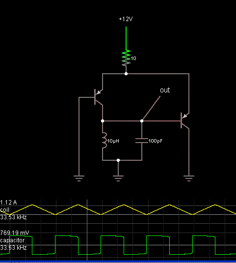
Hi - I have an inductor with a SRF around 1-10 MHz. I would like a circuit that can drive that inductor with a large amount of current at its self resonant frequency. I am still working on specifics, but the inductor will probably have an inductance of around 10-100uH. Driving voltage will probably be 12V or 24V.

I have seen many single transistor oscillator circuits that use an LC tank to set the oscillating frequency. These are perfect, except that they are driving very small amounts of current into the LC tank. I'm looking for much larger driving current, as this is to be used in a resonant wireless charging system. I'm thinking I'll have to drive the inductor with an H bridge, but I'm having trouble picturing the proper way of driving the bridge itself.

Does anybody have any suggestions?

Thanks!!
 

First order you need to understand the SRF mechanism of the inductor. I would either measure it or try to create a LCR model of it to understand what it is. Typical of a small inductor is a parallel LC which is high Z at resonance but large power inductors can be more complex. Let assume it is a parallel LC with a fair Q, it would require a high Z driving source at high voltage to get a large current though it. Once a model is available identifying a oscillator topography will be easier.
 

Pity you have no radio amateur experience! Amateurs know best how to handle such situation.

First of all, you are not allowed to radiate RF energy to "wirelessly charge" at any chosen frequency. Legally, there is the "industrial frequency", at 13.56 MHz, where you may work without a license.

Second, a "resonant coil" is not excited by 12 or 24 V but by a RF power generator. This generator typically has 50 Ohm output impedance, and your RESONANT CIRCUIT must be matched to it. At resonance and without a load, RF current in the coil can reach up to 1 kA and RF voltage up to 10 kV with RF input power between 10 and 100 W.

Such RESONANT CIRCUIT will then be loaded by radiation from the coil which can reach the SECONDARY resonant circuit located up to one-two meters away. Those two resonant circuits form a band-pass filter which, with a careful adjustment, also of coupling, can transfer a certain RF power to a load connected to the secondary circuit (a rectifier to charge a battery).

The DC to DC efficiency remains poor (several per cent), so to me the system wastes a lot of energy while causing a widespread RF interference around. All this to replace a DC charging cable!!!
 

What you need is a power RF transistor with a RF choke collector load, then a PI circuit feeding back to the base. Matching the collector Cap to the Z out of the transistor, and the base cap to the Zin of the transistor, it will go like the clappers and should get about 65% DC to RF conversion efficiency.
Frank
Hi Frank - I'm not sure I completely follow - where would my inductor be attached? Is it possible to draw up a quick schematic/sketch?

Thanks!!

- - - Updated - - -

First order you need to understand the SRF mechanism of the inductor. I would either measure it or try to create a LCR model of it to understand what it is. Typical of a small inductor is a parallel LC which is high Z at resonance but large power inductors can be more complex. Let assume it is a parallel LC with a fair Q, it would require a high Z driving source at high voltage to get a large current though it. Once a model is available identifying a oscillator topography will be easier.
Hi - this will be closer to an air core inductor than a power inductor. Goal is for Q to be > 20. Ideally more like 50-100. My expectation is that it can be modeled as a C in parallel with a R and L. So impedance should be: ZC || (ZL + R)
 

I have experimented with an LC tank oscillator found at the website:


(halfway down the page)

Here is a screenshot from my simulation (with the schematic redrawn):


One transistor carries load current through C-E which is normal usage. However the other transistor carries it through the base which is atypical, and which might ruin the transistor if the current is too great.

Addiontally this design is prone to stagnate if things are not right.

The coil and capacitor are in parallel, hence it could be said to resemble a coil which is arranged to self-resonate.
 

Aside from maximizing the coil impedance presented to the
driver, why do you care that it (the primary, in this wireless
charging scheme) is at resonance?

Given that the rolloff is fairly moderate in slope, is not (say)
a 10% error perfectly fine? And then if so, why not just
smack it around with a square wave drive and try to trap
the harmonics?

I think trying to combine oscillator and driver functions is
not what you want to do; you probably get the best of
neither.

Perhaps you want to track the -loaded- SRF because you
expect it to vary so widely that efficiency is compromised
if you drove it at any fixed frequency, when the load coil
moves or changes?
 

I have experimented with an LC tank oscillator found at the website:


(halfway down the page)

Here is a screenshot from my simulation (with the schematic redrawn):


One transistor carries load current through C-E which is normal usage. However the other transistor carries it through the base which is atypical, and which might ruin the transistor if the current is too great.

Addiontally this design is prone to stagnate if things are not right.

The coil and capacitor are in parallel, hence it could be said to resemble a coil which is arranged to self-resonate.

Looking at this design, I think that the frequency of oscillation is actually controlled more by the resistor, supply voltage, and inductance. I do not believe the capacitance plays a significant role.

- - - Updated - - -

Aside from maximizing the coil impedance presented to the
driver, why do you care that it (the primary, in this wireless
charging scheme) is at resonance?

Given that the rolloff is fairly moderate in slope, is not (say)
a 10% error perfectly fine? And then if so, why not just
smack it around with a square wave drive and try to trap
the harmonics?

I think trying to combine oscillator and driver functions is
not what you want to do; you probably get the best of
neither.

Perhaps you want to track the -loaded- SRF because you
expect it to vary so widely that efficiency is compromised
if you drove it at any fixed frequency, when the load coil
moves or changes?
The goal here is to hit the receiving coil with the receiving coil's SRF. I plan to use the same coil on the RX and TX side, so they should have the same SRF. Now that I type that, it gives me doubts that that is a good idea, since current in the TX will be much higher than in the RX. I could potentially just use any old coil on the TX side and just hit it with a very controlled frequency that matches the RX SRF.
 
Last edited:

Status
Not open for further replies.

Similar threads

Part and Inventory Search

Welcome to EDABoard.com

Sponsor

Back
Top