z_mx
Newbie level 5
hi everyone
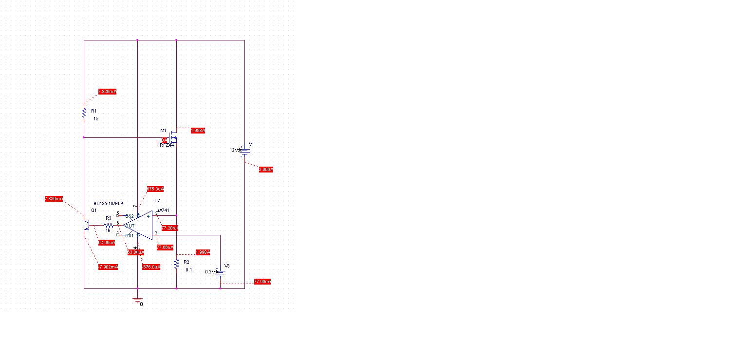
i need to develop constant current circuit (4A +-10%) in temperature range (-45 to 85 C). i mean constant current in temperature range, circuit will work 1 sec. supply voltage 28 V. main problem that my load can be from 1 to 7 ohm (random). i don't know if anybody here had experience this problem and should please guide me through..
thanx