Continue to Site

Welcome to EDAboard.com

Welcome to our site! EDAboard.com is an international Electronics Discussion Forum focused on EDA software, circuits, schematics, books, theory, papers, asic, pld, 8051, DSP, Network, RF, Analog Design, PCB, Service Manuals... and a whole lot more! To participate you need to register. Registration is free. Click here to register now.

I2C Problem. Multiple Slaves hang

Status
Not open for further replies.
Joined
Dec 4, 2012
Messages
4,280
Helped
822
Reputation
1,654
Reaction score
791
Trophy points
1,393
Location
Bangalore, India
Activity points
0
I have written a program in CCS C. It is for I2C communication between One Master PIC16F887 and two Slave PICs PIC16F887. When I use any one of the slaves the master reads the data from slave and displays it on masters uart but if I use both the slaves then it reads data from slaves and prints it on uart the first time and after that it reads 0 from the slaves and slaves hang. The i2c debugger shows that nack is being performed where ack has to be performed but If I use only one slave (any slave) then ack and nack happens properly as desired and I see data sent by slave is updated in master whenever the data in slave changes. Actually the slaves send the adc reading which is a float value.

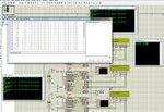
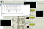
See the images. I have pointed where nack's is being performed if two slaves are used (first time the data is read properly after that it reads 0) The 0.0000 0.0000 is the data read the second time.
 

Attachments

  • i2c1s.jpg
    i2c1s.jpg
    667.3 KB · Views: 117
  • i2c2s_.jpg
    i2c2s_.jpg
    558 KB · Views: 134

Looks like a slave code problem at first sight, presumed Proteus is managing everything correctly.

Can show the slave code?
 

Here is the code for Slave. Both Slaves have the same code but the address value in #USE i2c is different.


Code C - [expand]
1
2
3
4
5
6
7
8
9
10
11
12
13
14
15
16
17
18
19
20
21
22
23
24
25
26
27
28
29
30
31
32
33
34
35
36
37
38
39
40
41
42
43
44
45
46
47
48
49
50
51
52
53
54
55
56
57
58
59
60
61
62
63
64
65
66
67
68
69
70
71
72
73
74
75
76
77
78
79
80
81
82
83
84
85
86
87
88
89
90
91
92
93
94
95
96
97
98
99
100
101
102
#include <16F887.h>
#device adc=10
 
#fuses HS, NOWDT, NOPROTECT, BROWNOUT, PUT, NOLVP
#use delay(clock=20000000)                //No low voltage prgming, B3(PIC16) or B5(PIC18) used for I/O
#use rs232(baud=9600, xmit=PIN_C6, rcv=PIN_C7, ERRORS)
#use i2c(SLAVE, SDA=PIN_C4, SCL=PIN_C3, address=0xA0) //FORCE_HW, stream=I2CS
 
#define LCD_ENABLE_PIN  PIN_D2                                    
#define LCD_RS_PIN      PIN_D0                                    
#define LCD_RW_PIN      PIN_D1                                    
#define LCD_DATA4       PIN_D4                                    
#define LCD_DATA5       PIN_D5                                    
#define LCD_DATA6       PIN_D6                                    
#define LCD_DATA7       PIN_D7
 
#include <lcd.c>
 
float temp = 0, old_val = 0;
int8 ctr = 0;
union float2bytes { 
    float fval; 
    int8  bytes[4]; 
} fvalue;
 
int8 data = '0';
 
BYTE addr, buffer[16]; 
 
#INT_SSP 
void ssp_interupt (){ 
   BYTE incoming, state; 
 
   state = i2c_isr_state(); 
        
   if(state < 0x80)                     //Master is sending data 
   { 
      incoming = i2c_read(); 
      if(state == 1)                    //First received byte is address 
         addr = incoming; 
    if(state == 2)                    //Second received byte is data 
        data = incoming;
       
    }
    //else if(state == 0x80){ 
      //i2c_read(); 
      //i2c_write('U');
    //}
    else if(state >= 0x80)                     //Master is requesting data 
    { 
      i2c_write(fvalue.bytes[ctr]);
      ctr++;
      if(ctr < 4)i2c_read();
      if(ctr==4){i2c_read(0); ctr = 0;}
      //i2c_write('M');
      
      
    } 
}
 
void main()
{
   int16 adc_val = 0;
   //set_tris_c(0xFF);
   setup_adc_ports(sAN0|VREF_VREF);
   setup_adc(ADC_CLOCK_DIV_2);
   setup_comparator(NC_NC_NC_NC);// This device COMP currently not supported by the PICWizard
   
   delay_ms(250);
   lcd_init();
   delay_ms(250);
   lcd_putc("\fSlave 1...\n");
   set_adc_channel(0); 
   delay_us(20);
   
   enable_interrupts(INT_SSP); 
   enable_interrupts(GLOBAL);
         
   while(TRUE)
   {
      adc_val = read_adc();
      delay_ms(20);
      temp = (float)(adc_val * 0.196078431372549);
      fvalue.fval = temp;
      if(old_val != temp){
         printf(lcd_putc, "\a%7.3f", temp);
         printf("Temperature is: %7.3f", temp);
         printf(" Degree Centigrade\r\n");
         printf("%7.3f\r\n", fvalue.fval);
         printf("%lu\r\n", adc_val);
      }
      if(data == 'K'){
         printf("%c\r\n", data);
         data = '\0';
      }
      //delay_ms(1000);
      old_val = temp;
      
              
   }
 
}


In CCS C i2c_read() performs ack and i2c_read(0) performs nack.
 
Last edited:

I see some differences to CCS example code respectively compiler manual suggestion given with i2c_isr_state():
- address isn't read for state == 0x80 (read address received)
- there are extra i2c_read() calls for state > 0x80

I must confess however that I didn't yet implement I2C slave functionality with CCS, thus I'm not aware of possible documentation faults. Another, partly unrelated question is how Proteus might handle possible I2C programming faults. I would primarly check all I2C issues with real PIC hardware and MPLAB debugger.
 

@FvM

I have tried it both in hardwrae and Proteus and have same problem in both. See the attached image. It is from the CCS C manual. It tells to perform read and write when i2c_isr_state() is 0x80.
 

Attachments

  • i2c_read1.jpg
    i2c_read1.jpg
    332 KB · Views: 118

See the attached image. It is from the CCS C manual. It tells to perform read and write when i2c_isr_state() is 0x80.
Yes. But your code doesn't follow the template. It doesn't read for state 0x80 and reads after write for state > 0x80.

I'm referring to post #3.
 

Ofcourse it reads for 0x80. I have used state >= 0x80. If I put the read before write in the if(state >= 0x80) condition then it is not working.
 

Ofcourse it reads for 0x80.
I can only comment the present code as written in post #3, not what might be intended or has been previously there and is commented out now.

Thus I can't but keep my statement in post #4 that your code differs in the said points from the CCS manual example.

Apart from the obvious C code differences, I would check what the CCS built-in functions are actually doing on the assembly level and if the sequence required by the Microchip manual is exactly reproduced. I have no doubt that PIC16 basically works in slave mode. So there's either a problem in CCS built-in functions, the CCS documentation or your code.

I assume, that besides documentation details, the Ex_slave.c code shipped with CCS C does work.
 

Status
Not open for further replies.

Similar threads

Part and Inventory Search

Welcome to EDABoard.com

Sponsor

Back
Top