Continue to Site

Welcome to EDAboard.com

Welcome to our site! EDAboard.com is an international Electronics Discussion Forum focused on EDA software, circuits, schematics, books, theory, papers, asic, pld, 8051, DSP, Network, RF, Analog Design, PCB, Service Manuals... and a whole lot more! To participate you need to register. Registration is free. Click here to register now.

Microcontroller for implementing a multiphase buck converter

Status
Not open for further replies.

vinayakdabholkar

Advanced Member level 4
Joined
Nov 29, 2009
Messages
114
Helped
0
Reputation
0
Reaction score
0
Trophy points
1,296
Location
goa
Activity points
2,195
Hello
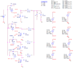
I want to implement a multiphase buck converter using a micro controller
My buck converter converts 12V to 1.2V at 12A switching frequency 500Khz
I went through TI and Microchips micocontrollers
I require 2 ADC and DAC and probably 8 PWM generator modules i think and 4 opamps and comparators
I am having difficulty in deciding the micocontroller as i am a newbee in this field
Please somebody suggest me a microcontroller for my needs
I had thought about PIC18F452
Will this be the right choice ?
I have attached the multiphase buck i am trying to built
 

Attachments

  • Multiphasebuck.png
    Multiphasebuck.png
    127.5 KB · Views: 116

intersil has multiphase pwm controllers too.I have experice of using pv3012 from powervation.
 

intersil has multiphase pwm controllers too.I have experice of using pv3012 from powervation.
I dont want to use a already available buck controller IC
I want it to implement myself using a microcontroller
 

There are no PIC18 controllers with 8 PWM channels.
Thanks. Checked that there are no PIC18 MCUs with 8 PWM channel
I was thinking dedicted channels will generate PWM with greater accuracy, so thought of having 8. I am still having major doubts about selecting the MCU
Wether to select 8 bit ,32 bit ?
My converter works at 500khz, so what frequency should the MCU have ?
A suggestion about a particular MCU will be helpful, i can then study it atleast
 

I just started using the PIC18F4520 and trying the ADC conversion in proteus and have many doubts
1) In proteus i have connected a 10MZ crystal with the HS configuration and i also see that when i edit the PIC settings in there is again a option for CPU clock there.
so which clock should i use, do i set both to 10Mhz ? or i set the CPU clock to 10Mhz/4 and keep the ocillator clock to 10Mz or i remove the crytal and set the clock to 10Mhz directly from the options ?
2) I just started with the ADC and needed some advice
I need the ADC conversion to occur as fast as possible. But it cannot be less than 1.6us as i suppose. For my clock of 10Mhz, Fosc/16=1.6us while Fosc/32=3.2us just to be safe i have chosen Fosc/32. Can i choose Fosc/16 and get accurate results ? . Also since my Tad is now 3.2us i have chosen acquisition time of 4Tad
To get fastest conversion and accurate conversion what changes i have to make ? which config gives the fatest results ?
 

Which Compiler are you using?
I am using Mplab ide v1.70 with xc8 compiler
I am having a problem with this code , i have attached the code and snapshot of the proteus simulation.
I cant seem to figure out what in the code is driving the pins RD0 and RD1 high
 

Attachments

  • Desktop.rar
    136.3 KB · Views: 86

Status
Not open for further replies.

Similar threads

Part and Inventory Search

Welcome to EDABoard.com

Sponsor

Back
Top