Continue to Site

Welcome to EDAboard.com

Welcome to our site! EDAboard.com is an international Electronics Discussion Forum focused on EDA software, circuits, schematics, books, theory, papers, asic, pld, 8051, DSP, Network, RF, Analog Design, PCB, Service Manuals... and a whole lot more! To participate you need to register. Registration is free. Click here to register now.

[SOLVED] GSM modem interfacing to AT89C51

Status
Not open for further replies.
hello tsea,

Its ok, don't be sorry :).
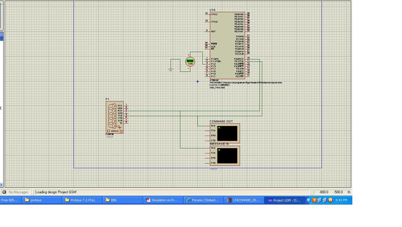
I checked it on proteus and it is working well :)


now there's problem with HARDWARE it seems. Even i think the the same but i found other info on the net, which was posted by some other member. i am posting it here.


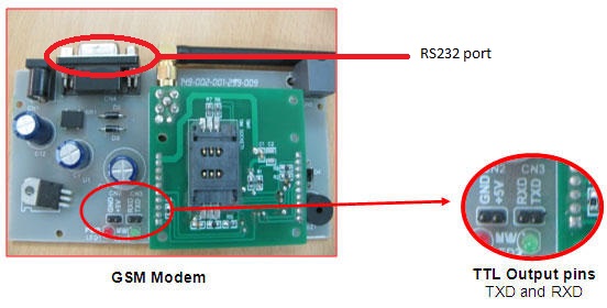
MAX232 is line driver chip it convert 5 volt logic into RS232 logic level and vice versa
controller understand the logic of 1 and 0
1 = 5 volt
0 = 0 volt

RS232 standard is
1 = - 6 to 25 volt
0 = + 6 to 25 volt

now you are giving these signals directly to 8051 so 8051 is not able to understand it
now you need one more MAX232 ic that will convert it to 0 and 5 volt logic that 8051 can understand


This suggests that i should use one more MAX232 but i don't think that i will need it :eek: here i am confused.


By the way, special thanks to you :) I will make sure that your name will be there in my report :) just let me know your name. i think tsea is your nickname.
 

yes that information is correct, I am sure that one needs to connect a microcontroller to RS232 standard via MAX232 but I am not sure about gsm modules. I think they have MAX232 chip already inside their circuit. so the Rx and Tx pins of GSM module are already at 8051 logic. one would need external MAX232 only if he would connect the microcontroller to serial communication port of gsm module(that 9 pin port, whose technical name is RS232) otherwise not. but you should check for that on net as I am not that sure. and yes tsea is my nickname and just put edaboard.com instead of my name ;) and to thank me, just help anyone whenever you can. good luck
 
yep i have came to the same conclusion :) i guess i have to connect MAX232 because i am connecting to RS232 connector of the modem.

By the way one doubt..
We both have implemented this on proteus but at that time we did not connect MAX232 in between micricontroller and Compim though it worked. how? :roll:

yes tsea is my nickname and just put edaboard.com instead of my name ;) and to thank me, just help anyone whenever you can. good luck

edaboard.com is already there :) :)
Yup i agree :) :)
Thank you :)
 

well yes you would need to connect your gsm module to microcontroller via MAX232 if modem would only have RS232 port. but it also has Tx and Rx pins,with GND that are at TTL logic. so use these pins, then you won't need any interfacing device like MAX232.
now about compim....
well I think compim does that itself i.e the function of converting TTL logic to RS232. but on the other hand,we also did not use a gsm modem inside proteus.if we would have used that, to show actual working, proteus would have required a MAX232 between microcontroller and gsm modem(if connection would be made via RS232 port of modem). so for devices outside proteus, I think compim itself performs that conversion but I am not sure,you should confirm. well to show you those Tx,Rx and GND pins I am uploading a picture. so you just need to connect Tx pin of your microcontroller to Rx pin of modem, Rx pin of your microcontroller to Tx pin of modem and GND to GND. goodluck
 
Last edited:

okay :smile: Thank you :cool:


well to show you those Tx,Rx and GND pins I am uploading a picture. so you just need to connect Tx pin of your microcontroller to Rx pin of modem, Rx pin of your microcontroller to Tx pin of modem and GND to GND. goodluck

one doubt again...
in proteus we connected Tx pin of microcontroller to Tx pin of modem, Rx pin of microcontroller to Rx pin of modem and GND to GND. but in hardware we connect like you said.. why? :???:
 

one doubt again...
in proteus we connected Tx pin of microcontroller to Tx pin of modem, Rx pin of microcontroller to Rx pin of modem and GND to GND. but in hardware we connect like you said.. why? :???:

good point amit... the first thing is....we didn't use actual modem inside proteus, compim was just a connector to connect the microcontroller to external devices. and yes in actual hardware the connections are different and are according to more common conventions that you would find in a number of books. i.e to connect Tx(transmit pin) of microcontroller to Rx(receiving pin) of modem and vice-versa. well it is very easy to remember this convention as the signals sent by microcontroller would be received by modem and those by modem would be received by microcontroller. now in proteus, I think that compim connector serves the purpose of an RS232 port for microcontroller side(other members please explain this if am wrong here) and thus one needs to connect same pins of microcontroller to its corresponding pins. although if one connects the actual hardware...he would need to connect in more common way, i.e Tx(microntroller) to Rx(modem) and vice-versa.
 

You don't have to use RS232 port on GSM module to connect to MCU. You can directly connect Rx and Tx pins of GSM Module to Tx and Rx pins of MCU.

Just see if there is headers given for Rx and Tx on GSM Module. Both your GSM Module and MCU should work at same voltage levels i.e., 5V or 3.3V. So, with TTL levels you directly interface GSM module with MCU. The wires will be crossed.
 

good point amit... the first thing is....we didn't use actual modem inside proteus, compim was just a connector to connect the microcontroller to external devices. and yes in actual hardware the connections are different and are according to more common conventions that you would find in a number of books. i.e to connect Tx(transmit pin) of microcontroller to Rx(receiving pin) of modem and vice-versa. well it is very easy to remember this convention as the signals sent by microcontroller would be received by modem and those by modem would be received by microcontroller. now in proteus, I think that compim connector serves the purpose of an RS232 port for microcontroller side(other members please explain this if am wrong here) and thus one needs to connect same pins of microcontroller to its corresponding pins. although if one connects the actual hardware...he would need to connect in more common way, i.e Tx(microntroller) to Rx(modem) and vice-versa.

oh i see :) yup i agree :)
Thank you tsea :) have a great day ahead :)

- - - Updated - - -

You don't have to use RS232 port on GSM module to connect to MCU. You can directly connect Rx and Tx pins of GSM Module to Tx and Rx pins of MCU.

Just see if there is headers given for Rx and Tx on GSM Module. Both your GSM Module and MCU should work at same voltage levels i.e., 5V or 3.3V. So, with TTL levels you directly interface GSM module with MCU. The wires will be crossed.

yeah i do agree. but i have to take connections via rs232 port only. there is no other provision i.e. no headers are given.......
 

hello friend i am intrested to make a project enotice board can you help me in interfacing sim300 with 8051 and code to display sms on lcd screen
 

hello... the various details that you are asking are already given and discussed in this thread....read from page 1. good luck ;-)
 

Status
Not open for further replies.

Similar threads

Part and Inventory Search

Welcome to EDABoard.com

Sponsor

Back
Top