Continue to Site

Welcome to EDAboard.com

Welcome to our site! EDAboard.com is an international Electronics Discussion Forum focused on EDA software, circuits, schematics, books, theory, papers, asic, pld, 8051, DSP, Network, RF, Analog Design, PCB, Service Manuals... and a whole lot more! To participate you need to register. Registration is free. Click here to register now.

Heater controlling system

Status
Not open for further replies.

syeda amna

Full Member level 4
Joined
Jun 1, 2010
Messages
222
Helped
24
Reputation
48
Reaction score
22
Trophy points
1,308
Location
Pakistan
Activity points
2,551
Hi
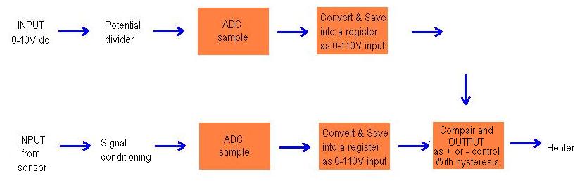
I want to design a controlled heating system with following specifications:
Input 0-10V
Output 0-110V
For increase in 1 degree temperature, will decrease the output upto 3V.

So anyone can guide me how i start working on this project. Is MATLAB will easy for doing this type of project. and what about hardware part? Please help me.
 

Is the input (0-10V) a signal from the sensor or is it the power source that varies with temperature? What temperature sensor are you using and where do you get the input from? Do you have any fixed voltage power supply to use?
 

The input is an ac or a dc signal. I will use ADC to convert it. I have to use AVR microcontroller. I never worked with temperature sensors before. I need help.
 

Does the signal come from the sensor? How did you decide that the input will be between 0V and 10V?
 

Will it change according to temperature? If so, what is the temperature range you plan to use?
 

Input voltage will not vary with temperatue.
At the output, temperature is an independent variable. As rise in 1 degree tempertue lowers the output voltage upto 3V.
If the input is 10V, output will be 110 (amplified by the factor of 11) and heater temperature goes up.
As temperature goes up, the output temperature decreases.
 
Last edited:

Then, is this input the power source from which the microcontroller and heating element will be run?

- - - Updated - - -

If the input is 10V, output will be 110 (amplified by the factor of 3)

How? 10 * 3 = 30
 

Sorry tahmid, i corrected my statement. Amplified by the factor of 11
10*11=110
 

There is some confusion do you have some model or any thing here for us to look into my friend even a block diagram will suffice
 

What you are asking for is not clear. Please explain in more detail.

Answer these questions and it may become clearer.

1) What is the input voltage (0-10V)?
2) Where does the input voltage come from? Why does it vary between 0V and 10V?
3) How does the output relate to the input?
4) What is your power source? What is its rating?
5) Does the output drive the heating element (heater)?
6) What is the power of the heating element (heater)?
7) Where does the sensor come into play?
 

Sensor is monitoring the heat from heater or the sensor and heater are separate?I am asking, if sensor is monitoring heat of one place and output is to power heater somewhere else.
In the first case there is no fix rate of output change as it only tries to maintain a set value.
In second case it is just like a power supply. It requires to generate output from zero to maximum voltage.This can be made using a switching device which is controlled by PWM, capable of delivering required output.
Software flow is like this.
Take input sample 0-10V,
Calculate to a equivalent to 110V change value.( A eight bit register stored with 0-220 values give a 0.5 degree resolution.)
Start PWM.
Take sample of this output through ADC of output generator.
Compare with the calculated result.
Vary the PWM output accordingly.
 
Sensor is monitoring the heat from heater or the sensor and heater are separate?I am asking, if sensor is monitoring heat of one place and output is to power heater somewhere else.
sensor is monitoring heat from heater.
can u explain more?
 

Then it is a simple thermostat. So you have 0-10V input. Other conditions, you described needs more clarification. You should be clear about the requirement. Only then a system is can be designed.
The input is an ac or a dc signal.
There will be different approach towards hardware and software for AC and DC. Similar is for output, is it AC or DC. Gather detailed specifications about the system. Get answers of what Tahmid has listed.
You should have details about,
Voltage and power ratings of input and output, control logic of the system. You cannot move on vaguely.
.As temperature goes up, the output temperature decreases
Do you mean 'as temperature goes up, the output drive to heater decreases.'
As rise in 1 degree tempertue lowers the output voltage upto 3V.
Heater have hysteresis, there are other algorithms to control heater such as PID. Decreasing output voltage in linear manner with respect to input is not the way as you describe or is it required ?
https://en.wikipedia.org/wiki/PID_controller


Try to describe your project operation as in this example.
Operation


The system works as described here. Upon start-up the system sets up the required internal hardware of the AVR micro and then read the EEPROM memory. If the EEPROM locations contain garbage values then they are set with default values otherwise the previously stored values are read. After reading the EEPROM, the system starts to monitor temperature and waits for actions if any temperature limit is exceeded. The system at this point shows current temperature and system status. If the user wishes to set parameters then he/she has to press the setup button and enter the settings menu. In the settings menu there are three settings and these are high and low temperature limits and the number of passes the system will make prior to issuing a fault message. If, for example, the high temperature limit is set to 40˚C, the low temperature limit is set to 20˚C and the number of system passes is set to 45, and the current temperature gradually rises to 41˚C from 30˚C, the system will trip high temperature alarm and start the cooler. The LCD display will show high temperature alarm. Now if the temperature starts to decline and reach a value in between (40˚C – (40˚C -20˚C)/2) =30˚C [i.e t_delta] and 20˚C within the 45 system passes then the cooler is turned off and no fault message is generated. The system resumes to normal state. If the temperature didn’t decline to the range mentioned as above then it is assumed that the cooler is either faulty or some other thing is causing too much heat generation which is exceeding the cooler’s capacity. Thus a fault warning is issued for the cooler and it is shut down until the fault has been cleared. In this way both the hardware and the cooler is protected from damage. The same scenario happens during the low temperature alarm. If both the cooler and the heater fail then the system goes in a complete halt state until reset or given attention.
https://embedded-lab.com/blog/?p=5515

**broken link removed**
 
Last edited:
Do you mean 'as temperature goes up, the output drive to heater decreases.'

yes, and it is necessary.

What you are asking for is not clear. Please explain in more detail.

Answer these questions and it may become clearer.

1) What is the input voltage (0-10V)?
2) Where does the input voltage come from? Why does it vary between 0V and 10V?
3) How does the output relate to the input?
4) What is your power source? What is its rating?
5) Does the output drive the heating element (heater)?
6) What is the power of the heating element (heater)?
7) Where does the sensor come into play?

1) Input is 0-10V
2) It is from power supply
3) output is amplified 11 times
4) power supply
5) Heater
6) It will be chosen such that it will drive from the output of the system
7) Sensor will detect the temperature and then controls the output according to temperature
 

Normally heater elements are not driven by th way, you are describing. If power source is ac, a triac or relay is normally used. A relay can control both ac and dc. Point is that, it is on/off control. Triac is used for phase control of ac.
Do you think it is something like this,
7128298600_1352720960.jpg
 
If your output is to be DC, you can create a DC-DC converter. A boost converter may suffice, depending on power. If output power is high (> 100-200W), it's better to use a transformer-isolated design. The output voltage should be adjusted by adjusting duty cycle.
Another way is to boost up the DC voltage to a fixed value and then adjust that by a second converter - this time, a buck converter. Again, adjust output voltage by adjusting duty cycle.

If you need AC output, you need to convert the stepped-up DC to AC. You can do this with a full-bridge converter.

Hope this helps.
Tahmid.
 
Status
Not open for further replies.

Part and Inventory Search

Welcome to EDABoard.com

Sponsor

Back
Top