Continue to Site

Welcome to EDAboard.com

Welcome to our site! EDAboard.com is an international Electronics Discussion Forum focused on EDA software, circuits, schematics, books, theory, papers, asic, pld, 8051, DSP, Network, RF, Analog Design, PCB, Service Manuals... and a whole lot more! To participate you need to register. Registration is free. Click here to register now.

AC lamp dimmer circuit?

Status
Not open for further replies.

Don_dody

Full Member level 1
Joined
Nov 4, 2012
Messages
96
Helped
1
Reputation
2
Reaction score
1
Trophy points
1,288
Location
Indonesia
Activity points
1,921
Can somebody tell me the circuit to vary the light intensity of 220 VAC lamp using microcontroller (PWM) ? I mean the connection and the dimmer circuit from microcontroller output to the AC lamp.
 

https://www.edaboard.com/threads/265546/
electronique_triac_001e.gif
 

modern regulators use FETs since thyristors cause more hindrances and acoustic noise.
**broken link removed**


Thanks. Actually I'm using Atmega8535 which is completed with PWM already. I'm interested with the second one, can you give me some explanation related to that picture?

- - - Updated - - -

modern regulators use FETs since thyristors cause more hindrances and acoustic noise.
**broken link removed**

I cannot read it and I don't understand. Is there any other link in English maybe?
 

Archive with scheme and firmware and source code (in AB) is located at the end of the article (**broken link removed**).
No link in English, but possible use the translation in Google.
 

We have been here before in a different thread.

PWM is not suitable for driving this circuit unless you slow the cycle period down to no more than the AC line frequency, even then the light will not dim but flicker or flash on and off according to the PWM duty cycle.

If you want to use phase control (which is what that circuit is for) change the opto-triac to a non-zero crossing type and trigger it by using a delay of up to (1/f) where f is the line frequency, from the zero crossing point.

Brian.
 

I cannot read it and I don't understand. Is there any other link in English maybe?

Use Google to translate it: **broken link removed**

PWM can be used, if it is at a high frequency and done on the mains input directly and then filtered to give a pure output. However, this may be overkill for a simple dimmer.

You may find it helpful to go through this: https://www.edaboard.com/threads/181497/

Hope this helps.
Tahmid.
 

Thank you for replying,

I've read the theory (phase angle control) but up until now I cannot build the digital dimmer circuit. Honestly don't know how to implement that theory to the real circuit. Can somebody help me with the circuit please?
Where I should connect the zero crossing detection?

I really appreciate all comments and suggestions.
 

You need to be able to detect the zero crossing. You can connect it to any input pin as long as you can somehow detect the zero cross. An easy way to do this is to use EXTERNAL INTERRUPT. Here's one way you can detect zero crossing: https://www.edaboard.com/blog/1807/

After zero-crossing, you need to wait a certain amount of time before you fire the triac. You can use a software delay or you can use one of the available timers. Then fire the triac. To do this, send a '1'. Use a delay. Then send a '0'.

Hope this helps.
Tahmid.
 

Dm.png

Well I got it, then, is this circuit ok or not for that concept?
 

The zero-cross detector in the MOC3031 won't allow firing at arbitrary angles. You can't use a zero-crossing optocoupler such as MOC3031 for phase angle control. Use a non-zero-crossing type such as MOC3021.

Why do you have R8? Remove it since supply voltage is 220V and load is a 220V lamp.
 

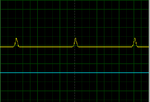
I've tried to build ZCD circuit and here is the result.
ZCD.png

What's wrong here???

This is the code:

#include <mega8535.h>
#include <delay.h>

interrupt [EXT_INT0] void ext_int0_isr(void)
{
PORTD=0x04;
delay_ms(2000);
PORTD=0x00;
};

void main(void)

{
DDRB=0x01;
PORTB=0x00;
DDRD=0x02;
PORTD=0x00;

GICR|=0x40;
MCUCR=0x01;
MCUCSR=0x00;
GIFR=0x40;

#asm("sei")

while (1)
{
PORTB=0x01; // flashing light on LED
delay_ms(1000);
PORTB=0x00;
delay_ms(1000);
};
}
 

Try this code:
Code:
#include <mega8535.h>
#include <delay.h>

interrupt [EXT_INT0] void ext_int0_isr(void)
{
   PORTD=0x02;
   delay_ms(2);
   PORTD=0x00;
};

void main(void)

{
   DDRB=0x01;
   DDRD=0x02;
   
   GICR|=0x40;
   MCUCR=0x01;
   MCUCSR=0x00;
   GIFR=0x40;

#asm("sei")

while (1)
      {
      PORTB=0x01; //  flashing light on LED
      delay_ms(1000);
      PORTB=0x00;
      delay_ms(1000);
      };
}

Make sure you connected the zero-cross signal to INT0 (PD2). Observe output at PD1.

Hope this helps.
Tahmid.
 
What is the frequency of the zero-cross signal? Did you use a 50Hz/60Hz AC source? I think you mistakenly used about 600Hz instead.
 

It is 50Hz 220V

Freq.png

- - - Updated - - -

Can you explain me what is actually your code do ??
What is my mistake ?? so i can learn..
 

Then, you probably didn't set the ATMEGA oscillator settings properly. Double click the ATMEGA and set the correct settings. Use the same frequency that you used in your program.

- - - Updated - - -

You used a 2 second delay in the interrupt. You must always keep interrupts as short as possible. Plus, you must fire every cycle. So, why 2 seconds?

In the interrupt you set PORTD 2, then used a delay and then cleared PORTD 2. However, PORTD 2 is the external interrupt pin INT0 that you configured interrupt for. So, I used PORTD 1 instead as the output pin.
 

I've never change the setting before, this is the default setting
8535.png


Well I see,

For interrupt, so that mean the output pin must always PORTD 1 ?
 

Status
Not open for further replies.

Similar threads

Part and Inventory Search

Welcome to EDABoard.com

Sponsor

Back
Top