Continue to Site

Welcome to EDAboard.com

Welcome to our site! EDAboard.com is an international Electronics Discussion Forum focused on EDA software, circuits, schematics, books, theory, papers, asic, pld, 8051, DSP, Network, RF, Analog Design, PCB, Service Manuals... and a whole lot more! To participate you need to register. Registration is free. Click here to register now.

Need help :: FULLY-CONTROLLED SINGLE-PHASE SCR BRIDGE RECTIFIER: RL LOAD

Status
Not open for further replies.
No sir , Our project need this negative as full as positive .. !!

I post the photo that require for output !

did you see it ?! here it is View attachment 82650

- - - Updated - - -

Our project depends on DC MOTOR on the load

- - - Updated - - -

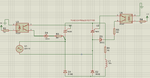
Also , I don't get it form your design ,, when you put the same component in the upper 2 thyristors but in other hand of the lower 2 thyristor in completely different connection form the opto-coupler into thyristor !! 8-O

you can see from your design U2 & U4 are the same .. and U1 & U3 are the same but not the same for all of the thyristor ?!

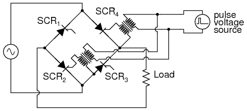
why we just but the same material for the full bridge ..

Then this is not a at all rectifier............
 

Then this is not a at all rectifier...
People actually use to name it controlled rectifier.

But your optocouplers don't have 400V or so voltage rating, isn't it? Trigger transformer is the classical solution, opto triacs can be used if dV/dt is low enough to avoid self-triggering.
 

People actually use to name it controlled rectifier.

But your optocouplers don't have 400V or so voltage rating, isn't it? Trigger transformer is the classical solution, opto triacs can be used if dV/dt is low enough to avoid self-triggering.


Is that the image i mentioned is controlled rectifier ? ? ?

- - - Updated - - -

Gate reference here is floating... View attachment 93746.....I want to control the scr from microcontroller which has separate grounding. I dont want to mix the Microcontroller Ground with High voltage ground. How to do it..
I think the gate current need to flow in microAmps with respect to Cathode of scr. But Cathode of SCR is in +Ve output of DC voltage.. Help me in this regard

Small change could help you....... Invert the logic in the output
trig..JPG
 

In the circuit you shown, the Cathode is connected to ground, so you can get the zero referencing...But look at the controlled bridge rectifier, the cathode of SCR is not connected to ground, It is connected to the power + Bus DC Voltage. So your circuit is not applicable to this case. Plz think it again. Thanks for the reply
 

Attachments

  • controlled Rectifier.png
    controlled Rectifier.png
    63.4 KB · Views: 121

In the circuit you shown, the Cathode is connected to ground, so you can get the zero referencing...But look at the controlled bridge rectifier, the cathode of SCR is not connected to ground, It is connected to the power + Bus DC Voltage. So your circuit is not applicable to this case. Plz think it again. Thanks for the reply

Forget the Ground it does nothing here... The relevent ground in your circuit is SCR cathode It will work with the negative voltage came from another limp Diode.... try in simulation...
 

So what you say...The circuit i connected the SCR with optocoupler will work...???
Cathode is not in the negative voltage it is in +Bus of DC Voltage.controlled Rectifier.png
 

Clearly look at it for U1 the D2 will ON and the positive rail will be negative before U1 turn ON and for U1...
 

The circuit i connected the SCR with optocoupler will work...???
It can't work, for the simple reason that no transistor opto-coupler stands 300 or 400 V. I already mentioned this in post #42, don't know if you just ignored the comment or don't understand the problem. :-(

P.S.: I don't discuss the meaningless case shown in your schematic, where the opto coupler LEDs are always powered . If we want the thyristors permanently turned on, we place diodes instead.
 
Last edited:

It can't work, for the simple reason that no transistor opto-coupler stands 300 or 400 V. I already mentioned this in post #42, don't know if you just ignored the comment or don't understand the problem. :-(

P.S.: I don't discuss the meaningless case shown in your schematic, where the opto coupler LEDs are always powered . If we want the thyristors permanently turned on, we place diodes instead.

I clipped some part in #39.. that uses separate 5V source for firing SCRs(from micro controller)..
optocoupler never works in main voltage...

And if you want without any sources means convert your outputs into pulse train(by and logic with some frequency) and then give it through a pulse transformer...

**broken link removed**

03221.png
 

In the second diagram , Another end of secondary side of Pulse transformer is connect to AC line..It is dangerous, that High voltage AC line is directly connected to Return path of pulse transformer. It may be OK for some theoretical explanation But It will not work in practical application.

- - - Updated - - -

- - - Updated - - -

It can't work, for the simple reason that no transistor opto-coupler stands 300 or 400 V. I already mentioned this in post #42, don't know if you just ignored the comment or don't understand the problem. :-(

P.S.: I don't discuss the meaningless case shown in your schematic, where the opto coupler LEDs are always powered . If we want the thyristors permanently turned on, we place diodes instead.


No..Its not meaningless...I connected +5v just for showing , will be coming from microcontroller...It is not permanently giving with +5v it is coming from digital input...
 

In the second diagram , Another end of secondary side of Pulse transformer is connect to AC line..It is dangerous, that High voltage AC line is directly connected to Return path of pulse transformer. It may be OK for some theoretical explanation But It will not work in practical application.


That is just an example circuit... in your circuit it will be on the +ve rail, and also i never seen a problem when one end of pulse transformer connected in a phase...

And the important thing, you have quickly remove MCs 5V for firing, because it will link with rectified +ve rail and can damage your MC in any moment... use a separate source or go for pulse transformer....
 

In the second diagram , Another end of secondary side of Pulse transformer is connect to AC line..It is dangerous, that High voltage AC line is directly connected to Return path of pulse transformer. It may be OK for some theoretical explanation But It will not work in practical application.
I wonder if I missed something in the schematic? The secondary side is connected to AC line, that's no problem. The primary side is isolated. It's not just a theoretical explanation, it's a fully working circuit.
 

You can do it with a single SCR connect the load in series with a diode bridge and connect an SCR between positive and negative outputs of the bridge Very easy
 

You are saying pulse transformer when connected to phase is not a problem....Its strange , 230VAC !!!...But let me check in hardware....
Big problem in that circuit, It may be fire the SCR but after turning on the Secondary of the pulse transformer voltage will induce a voltage on the primary which ll destroy the circuit connected to primary....

- - - Updated - - -

You can do it with a single SCR connect the load in series with a diode bridge and connect an SCR between positive and negative outputs of the bridge Very easy

SingleSCR.png

It also have the same problem, Floating Cathode!!!!
 
Last edited:

Status
Not open for further replies.

Part and Inventory Search

Welcome to EDABoard.com

Sponsor

Back
Top