Continue to Site

Welcome to EDAboard.com

Welcome to our site! EDAboard.com is an international Electronics Discussion Forum focused on EDA software, circuits, schematics, books, theory, papers, asic, pld, 8051, DSP, Network, RF, Analog Design, PCB, Service Manuals... and a whole lot more! To participate you need to register. Registration is free. Click here to register now.

regarding Polyphase filter

Status
Not open for further replies.

Manjularamkumar

Member level 1
Joined
Aug 16, 2011
Messages
34
Helped
0
Reputation
0
Reaction score
0
Trophy points
1,286
Activity points
1,507
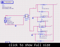
I am designed RC single stage polyphase filter using ADS for producing quadrature phases.

I didnt get correct phases eventhough i used the formula w= 1/RC.

I gave the balance signal. How to get the correct phases. See my diagram .Plz anyone tell me where i did a mistake?
 

Attachments

  • PPF1.bmp
    3.8 MB · Views: 97

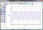
I made a simulation. By grounding one end of the AC source, you eliminate outputs 3 and 4.

I removed the ground at the AC source. Now all 4 outputs show a signal. These are out of phase, each 90 degrees from the next. I believe this is what you want.

You still need the two zero grounds at the RC network. I removed them, and suddenly all four outputs became nearly in phase with each other.
 

The circuit should work fine if the balun gives a balanced output.

Here's the circuit for anyone who doesn't want to download a 3.75MB bitmap:

 
  • Like
Reactions: FvM

    FvM

    Points: 2
    Helpful Answer Positive Rating
Polyphase_dds.png

The circuit as O/P posted works correctly, after allowing for the start-up transients for the simulation. If the ground on the 1 tone source is removed then signals at the output are still present but at different amplitudes. Two of the output signals are missing if the 1 tone source +ve pin is connected to the common-mode pin (c) of the balun. The +ve pin should be connected to the differential mode pin (d).

Looking at the VspecTran measurement may be confusing though as it only shows the magnitude of the signal and not the phase.

Actually for this application with a grounded common-mode pin to the balun it is recommended in the documentation to use the Balun3Port instead of the Balun4Port as it provides "an equivalent, but numerically more robust" result. Both work in this example though.
 
Last edited:

Status
Not open for further replies.

Similar threads

Part and Inventory Search

Welcome to EDABoard.com

Sponsor

Back
Top