Continue to Site

Welcome to EDAboard.com

Welcome to our site! EDAboard.com is an international Electronics Discussion Forum focused on EDA software, circuits, schematics, books, theory, papers, asic, pld, 8051, DSP, Network, RF, Analog Design, PCB, Service Manuals... and a whole lot more! To participate you need to register. Registration is free. Click here to register now.

Low level AM Transmitter Circuit and little description.

Status
Not open for further replies.
@ goldsmith
If you need a complete circuit , i have thousands of these circuits in my designs . i can give you some of them easily , but you have told that you want learn , it is the reason that why i didn't give you the final circuit !
Actually, I really want to learn something, but I have no much time. Till the day after tomorrow I will have to submit a proposal, in which two major things are included,
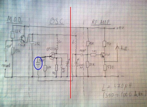
1) circuit diagram of the low level AM Transmitter.
2) costs of components used in the circuit diagram of the low level AM Transmitter.
I want you (goldsmith) provide me a simplest low level AM transmitter, so that I could prepare my proposal and show the circuit diagram to my teacher by 5th of September, with following conditions,
1)AM transmitter should be low level,
2)It must not use any crystal anywhere in the circuit,
3)Range must be at least 30m.
4)carrier oscillator must be simple i.e. with RC dependent circuit (as my teacher told)

Then after 5th September I have more 3 weeks to assemble the whole circuit on the breadboard, during this time you can teach me briefly about the circuit i.e. about major portions. But I urgent need a complete and simple low level AM transmitter circuit with 30m of range without any use of crystal (as underlined above).

Yes shayaan have told me regarding this issue , and i told him that here is the same too ! ( an advice : try to learn yourself , instead of trying to rely on teachers of your university ! )
By the way where is shayaan now ? is he busy too ? because i didn't see him here any more ( this month ) .
Yes, your advice is pretty appreciable. I think in the same way as you. And Shayaan's internet is not running. His internet is crap and now it is stopped that's why he is not come to the forum, as he told me that he is making a project (audio amplifier under supervision of goldsmith) but he is out of internet service.

@ FvM
Searching for "AM transmitter" at electronic boards and google will give you plenty of hits, possibly more than you can handle. Below two arbitrary links with some background information about antenna tuning and legal aspects.

**broken link removed**

Of course, if the project stays with pencil and paper, there's no legal issue. Before going to operate real stuff, I would expect some legal information from the teacher.
Thank you. Well I have already seen these links and don't like circuit because they don't satisfy my conditions (i.e. proposed by my teacher)

@ LvW
I have the feeling that you are under strong time pressure now. Of course, all of us want to help you - however, it is not easy for us because lack of information.
Thank you that you can feel this, I appreciate all of you people' help. What information you want please tell me I will try to provide, as I have no much time, now I have just 2 days remaining in submitting of the proposal.
You are allowed "to use those Integrated Circuits which are studied under course named "Linear Integrated Circuits"(LIC)."

How could we know which IC's you have studied?
What means "741C etc".
We have studied basic op-amp i.e. 741C. So we can use any op-amp.

For example, are you allowed to use a fast opamp with at least 10 MHz transit frequency? Remember: The 741 has only 1 MHz.
This is important because for carrier frequencies in the range of several hundreds of kHz the 741 cannot be used.
Of course, as an alternative you can use discrete transistors (instead of opamps) - but the design is more complicated.
Therefore, I have recommended an opamp based design (two units: Oscillator and differential amplifier IC). But you need a broadband opamp (as mentioned above).
Today, I personally asked my electronic communication teacher that you forbid us to use crystal oscillator so can we use Hartely, Colpits, Wein-bridge or phase shift oscillator. So he replied, don't use integrated circuits, although we have studied op-amp but he refused to use these types. He further said, use simple RC network to generate carrier, as goldsmith showed in post#18.
 
Last edited by a moderator:

He further said, use simple RC network to generate carrier, as goldsmith showed in post#18.
Post #18 shows a colpitts type LC oscillator. A LC oscillator has the advantage of better frequency stability compared to a simple RC (e.g. phase-shift) oscillator. It even allows a self-oscillating output stage with modulation. But a transistor RC carier oscillator is possible, in this case the output/modulator stage should be separated.

Inductors may be also helpful to increase output power and match an antenna, completely avoiding them sounds like a bad idea.
 

Inductors may be also helpful to increase output power and match an antenna, completely avoiding them sounds like a bad idea.

From Eshal's postings I've got the feeling that he urgently needs a working AM transmitter concept (within the next two days).
Perhaps I am wrong, but I think he should not pay to much attention to frequency stability, increased output power and matching aspects.
Instead, I would try to find a concept which (a) is relatively easy to understand (for a beginner like Eshal) and (b) relatively simple to design and to tune.
I am not sure if - within the remaining time - he would be able to design a working AM transmitter on a pure transistor basis
That is the background of my recommendation to use a simple opamp oscillator and an integrated diff. amplifier chip for modulation (a transconductance amplifier, OTA, would also do).
 

I agree about the straightforward design of OP oscillators. But apparently he wants a transistor oscillator. RC phaseshift and LC are pretty easy as well.

I build hartley LC oscillators as a schoolboy, tuneable with a single variable capacitor over a wide range, modulated by an astable multivibrator, working well as radio and TV jammer.
 

These are all https://www.google.ca/search?num=10...20&bih=993&q=am+transmitter&oq=am+transmitter
examples of AM transmitters.

Choose AM receiver for testing and transmit in low range of 530~1400 KHz.

If you want to play with some logic inverters, you can make them oscillate in this band easily and then modulate the output with a microphone and use any long wire for antenna.

Clock Use any small inductor and compute f from 1/(2pi sqrt(LC) where if C1=C2, C=1/2 C1
LC more stable than RC oscillator. and Ceramic resonator more stable than LC.

**broken link removed**
Mic amplifier may use pullup DC resistor (~5K) from electret mic to V+
Adjust pot for Modulator should be < 90% with peak audio.
vectro.gif


use any supply such as 9V battery with Cap.
Add 470 ohm resistor between clock and base of Q1.
With no jumper, replace all series inductors with 1 in range of 1~1.5mH.
Reference
https://www.geocities.ws/raiu_harrison/mwa/tech/circuits/vec1290k.html
 

I am not sure if - within the remaining time - he would be able to design a working AM transmitter on a pure transistor basis...
He doesn't need to design anything. His teacher told him to find a circuit on the internet. I'm sure there are plenty of simple, tried and tested circuits out there. Unfortunately he seems unwilling to put in the small amount of effort required to find one.

I've got the feeling that he urgently needs a working AM transmitter concept...
Yes, that's what he needs, but what he wants is:

I want you (goldsmith) provide me a...
Oddly enough I don't think he even bothered to look at the oscillator circuit Goldsmith showed him, otherwise he would have noticed it had an inductor in it.

Frankly I'm not sure anyone so lazy and disinterested deserves to succeed with his project.

I build hartley LC oscillators as a schoolboy, tuneable with a single variable capacitor over a wide range...
Likewise, those were lots of fun! :grin:

Now, how come we could do that just for fun as schoolboys but today a 4'th semester electrical engineering student can't, even with a world of information at his fingertips via the internet (which we didn't have)?

Maybe it's just because we were motivated enough to read and to learn.
 
  • Like
Reactions: FvM and LvW

    LvW

    Points: 2
    Helpful Answer Positive Rating

    FvM

    Points: 2
    Helpful Answer Positive Rating
godfreyl [I said:
Now, how come we could do that just for fun as schoolboys but today a 4'th semester electrical engineering student can't, even with a world of information at his fingertips via the internet (which we didn't have)?
Maybe it's just because we were motivated enough to read and to learn[/I].

Yes, godfreyl - I have no other choice than to agree with you. I am afraid, you have described in two sentences the today's situation. It would be interesting to see some answers to the question "why is it so", but that's beyond the scope of this thread.
 
Last edited:

hi,
take a look at a AM transmitter i built in the past..... It was intended to transmit 1kHz signals but later i used it to transmit music and it works fine (over 30% modulation i have little distorsions). I personally used it over ~50 m (from my house to the place i go fishing :grin: ) , with 5 m long wire antenna (simple wire that i unwinded from a coil)
 

Attachments

  • Photo0547.jpg
    Photo0547.jpg
    551.5 KB · Views: 160

@ FvM
Post #18 shows a colpitts type LC oscillator. A LC oscillator has the advantage of better frequency stability compared to a simple RC (e.g. phase-shift) oscillator.
So can I use in place of 1MHz and 15KHz signal source (post#4 of goldsmith)?

I agree about the straightforward design of OP oscillators. But apparently he wants a transistor oscillator. RC phaseshift and LC are pretty easy as well.
Yes yes, I need transistorized oscillator.

@ LvW
From Eshal's postings I've got the feeling that he urgently needs a working AM transmitter concept (within the next two days).
I am not HE. I am SHE. :)
That is the background of my recommendation to use a simple opamp oscillator and an integrated diff. amplifier chip for modulation (a transconductance amplifier, OTA, would also do).
Although we have studied op-amp and OTAs but our teacher refused to use them in the circuit. He want circuit with just passive components and with transistor. :-(

SunnySkyguy
Sorry, your post is not related to my task, it is for advanced users, I ain't :-(

@godfreyl'
He doesn't need to design anything. His teacher told him to find a circuit on the internet. I'm sure there are plenty of simple, tried and tested circuits out there. Unfortunately he seems unwilling to put in the small amount of effort required to find one.
No, I am not unwilling to find circuit on the internet. I therefore not did so, because I want you people that you give your circuit and teach your circuit to me. One more thing, as I am not good in electronics because it is our 4th semester, it is our first project. So I don't know what things must be considered. Therefore, I turned to this forum that I will describe my conditions, situations and problems to you experts and you will easily help me out of this. This is the reason, I didn't search internet.
My all class fellow searched. But I want something different.

Oddly enough I don't think he even bothered to look at the oscillator circuit Goldsmith showed him, otherwise he would have noticed it had an inductor in it.

Frankly I'm not sure anyone so lazy and disinterested deserves to succeed with his project.
I am not lazy. :-( :-( :-(

- - - Updated - - -

@ zsolt1
hi,
take a look at a AM transmitter i built in the past..... It was intended to transmit 1kHz signals but later i used it to transmit music and it works fine (over 30% modulation i have little distorsions). I personally used it over ~50 m (from my house to the place i go fishing ) , with 5 m long wire antenna (simple wire that i unwinded from a coil)
This is what I was looking for. Now I'm at least able to prepare proposal for the day after tomorrow.
Does it really provide a ~50m?

Can you explain the working of 3 stages as you mentioned in the circuit diagram?

Is it low level? 15v of power supply indicates it is low level, I think.

What is the impedance of antenna.

Kindly clear these text marked in colorful circles below.
Is it mic?
What is this value?
Is this the modulator section?
Is this 2.2nF?
What are the values of these inductors?
Is it transistor? What is the code of this?
Is it 10K?
Can you tell me about this calculation what is this?
This is oscillator section. Right?
This is RF amplifier. Right?

- - - Updated - - -

Untitled.jpg

Sorry. I have seen the values of inductors in the right bottom corner.

By the way thank you a lot. :)
 

Post#12: I am just allowed 555 timer, 741C etc. In short, I am allowed to use those Integrated Circuits which are studied under course named "Linear Integrated Circuits"(LIC).

Post#29: Although we have studied op-amp and OTAs but our teacher refused to use them in the circuit. He want circuit with just passive components and with transistor.

Such specifications make the help a bit problematic.
 

hi,
lets see... about the oscillator its built with the BF244 A j-fet tranzistor, its frequency can be modified with the tandem 365 pF condensator (its a variable condensator from old radio with two compartiments -2 caps in 1 shaft-) it is pretty stable :grin:
From where is the oscillator supplied ? From the modulator built with the bc548 tranzistor which is in a emiter folover configuration, so when no signal is applied to its base this transistor supplies the oscilator with ~6 V because it has the static operating point set by the 22K & 15K rezistors from the base. With the oscilator supplied with 6V, it oscilates with the preset frequency (set by the 365 twin caps) at a given Amplitude. When signal applied to the input of the modulator (I used to put there signal from my PC) the static operating point varies with the input signals amplitude.Since the modulator is in emiter folover configuration, it will supply the oscilator with a voltage that has the same form of variations. Since the oscilator has a stabile frequency (do its construction & type), only the amplitude of its oscilations will vary in the same way like the signal from the input of the modulator . You have AM :grin: . Further the modulated signal is amplified by the last bc 548 from the RF amplifier.
colors:
1 & 2 : 1 = input terminals; 2 = is the input cap (it separates dc from the input of the modulator, because only ac passes thru cap by polarization of dielectric ......... -long story-)
3- yes it is the modulator section
4- yes 2.2nF
5- the values are not critical .With the values of the inductors and the variable double cap (365pF) you set the frequency of oscilation
6- BF 244A (j=FET)
7- 10 K
8- grossly you can use the thompson formula or ... simply f=159/ sqrt (L x C) [MHZ] ; where L in [uH] ; C in [pF] . If C is variable capacitor (like in this case) you take its minimum value to get the maximum value of tuning frequency & you take its maximum value to get the minimum tuning frequency of the LC resonant circuit , so you know the limits betven you can set the frequency of your oscillator. I sed grossly because souch oscillators have specific formula to calculate their frequency .... (see oscilator types on google -colpitts, hartley...... -)
9 -yes
10 -yes
_________________________________________________________________________________________________________________________
Ps: i think it goes more than ~ 50m .. I aplied audio signal from my pc (scr**mer internet radio), the antenna was a piece of simple cooper wire. For the reciver i used a old radio reciver (made in URSS) I did not go further than ~50 m since my fishing place was not so far away ...

- - - Updated - - -

I do not belive school boys and girls are dezinterested since they ask on forums about solutions for problems . I think (and know in some particular cases) that teachers could do some more ....
Maybe we people could do some more around us, and here to ... :wink:
 
Last edited:

Hi again
And Shayaan's internet is not running. His internet is crap and now it is stopped that's w
Perhaps mouses have eaten the wires !!!! some times ago some mouses tried to eat communications wires here ! and my internet was out of service for long time !
Zsolt's circuit seems ok ! if you just want transistor . but if it is not critical to don't use anything unless transistor , sunnyskyguy's circuit is good too . but don't forget for AM transmitters with low frequency , such as 1 MHZ , you will need a long antenna , and i think a dipole antenna ( lambda/2) would be ok , for your aim , however it's distance can't be as it should be !
Good luck
Goldsmith
 

@ LvW
Post#12: I am just allowed 555 timer, 741C etc. In short, I am allowed to use those Integrated Circuits which are studied under course named "Linear Integrated Circuits"(LIC).
Yes, I must be free to choose op-amp as I have studied them, our LIC teacher studied us these.

Post#29: Although we have studied op-amp and OTAs but our teacher refused to use them in the circuit. He want circuit with just passive components and with transistor.
But our analog communication teacher refused to use op-amp.
I was thinking may be I can use op-amp in my circuit somewhere. But when I personally asked to my communication teacher then he refused to use them.

@ zsolt1
Nice explanation. I understood it very much. Thanks for help.
2 = is the input cap (it separates dc from the input of the modulator, because only ac passes thru cap by polarization of dielectric ......... -long story-)
Please tell me the value of this capacitor. Is that 100pF?

grossly you can use the thompson formula or ... simply f=159/ sqrt (L x C) [MHZ] ; where L in [uH] ; C in [pF] . If C is variable capacitor (like in this case) you take its minimum value to get the maximum value of tuning frequency & you take its maximum value to get the minimum tuning frequency of the LC resonant circuit , so you know the limits betven you can set the frequency of your oscillator. I sed grossly because souch oscillators have specific formula to calculate their frequency
Please tell me more about this. I don't know what is Thompson formula.

is it not necessary to know the impedance of the antenna?

By the way, great help. But I think, I need more. I will refer to the forum again.

- - - Updated - - -

@ goldsmith
Perhaps mouses have eaten the wires !!!! some times ago some mouses tried to eat communications wires here ! and my internet was out of service for long time !
No, here ISP's problem.

So for my low level, should I use long antenna?

@godlsmith can you help me with zsolt1's circuit?
 

the input capacitor is 100 nF
it's about william thomson 's (i miss spelled his name ) formula for LC resonace frequency calculation, see https://en.wikipedia.org/wiki/LC_circuit (skip the fancy matematic part ...)
About the impedance of the antenna.... when using a antenna which is calculated so that it is accorded on the transmitter frequency , you'we got high efficiency ...... (the antenna mostly radiates the useful signal (information carrier signal), armonics are attenuated ......)
When using any antenna (like i did ) your sistem is not very efficient you loose a lot of power of your signal (maybe the peace of wire i used had the correct length and diameter :-D )
Anyway antenna calculations are bulky (even the position of the antenna from the ground meters and there are also some propagation issues to consider) and special high frequency equipments are needed to measure radiation, reflection ...... I am not realy an expert in this so i can not provide souch detailed information.
 

I am not realy an expert in this so i can not provide souch detailed information.
But you can at least tell me what type of antenna you used.
how long should it be and what about the diameter of the loop in the antenna?
 

But you can at least tell me what type of antenna you used.
He used a copper wire, 5m in length. There is no loop in it. It is just a straight(ish) wire, lifted as high as possible.

If you want to use zsolt1's circuit, there is a more important problem. In the circuit diagram, there is no obvious way for the signal to go from the oscillator to the amplifier. In the picture below, you can see there is no signal path crossing the red line from left to right. Maybe the two coils must be coupled, or maybe there is a connection that is not shown on the diagram. Hopefully zsolt1 will explain.

Note, the capacitor circled in blue connects one side to the other, but it is to bring feedback to the gate of the JFET. It is not coupling the oscillator output to the amplifier.


If you want to use zsolt1's circuit, there is a more important problem. In the circuit diagram, there is no obvious way for the signal to go from the oscillator to the amplifier. In the picture below, you can see there is no signal path crossing the red line from left to right. Maybe the two coils must be coupled, or maybe there is a connection that is not shown on the diagram. Hopefully zsolt1 will explain.
Yes, I also noticed that point. But zsolt1 says he is good with this circuit so I didn't talk further about this problem

Can anyone tell me that how much wattage of resistors are used there?
 

So for my low level, should I use long antenna?
Hi Eshal
Your antenna , should be as long as possible ( it can be until lambda/4 ) . so , if you increase it's size , the result will be pretty better .
@godlsmith can you help me with zsolt1's circuit?
Sure , but what is your problem with that ? that is a simple oscillator and an RF amplifier , and a simple series transistor ( to add message signal into DC signal ) . what section is your problem ?
Best Luck
Goldsmith
 

should be as long as possible ( it can be until lambda/4 )
What do you mean by lambda/4. I didn't listen this word before..

Sure , but what is your problem with that ? that is a simple oscillator and an RF amplifier , and a simple series transistor ( to add message signal into DC signal ) . what section is your problem ?
Can you tell me how much wattage of resistor should I use in the zsolt1's circuit?
And its power supply is +15v. So this implies that it is a low level. Can you tell me till how much value of supply the transmitter is recognized as low level. For example, if a transmitter with +35v then would it be regarded as low level transmitter or high level?
 

Hi Eshal
What do you mean by lambda/4. I didn't listen this word before..
Lambda ? it is wavelength . it will given from the formula :( 3*10^8)/F it is according to the meter . an example : consider you want transmit 27 MHZ , sine wave . it's lambda , is 3*10^8/27*10^6=11 meter
So , if you use an image reflected antenna ( lambda/4 ) it's dimension will be 11/4 =2.75 meter . it will be just a wire . but if you use dipole antenna , lambda/2 you will have two wire . first one is ground and the other one is out put . distance of your antenna will be 11/2=5.5 meter . it means two wire with 2.75 meter size . or each other kind of antenna ! but for transmitters at high powers , and frequency of HF band , most of the time , most reasonable choice is lambda/2 antenna . ( didn't you have telecommunications in university ? or perhaps didn't you read any book regarding this issue ever ?)
Can you tell me how much wattage of resistor should I use in the zsolt1's circuit?
Which resistor you are referring to ?
And its power supply is +15v. So this implies that it is a low level. Can you tell me till how much value of supply the transmitter is recognized as low level. For example, if a transmitter with +35v then would it be regarded as low level transmitter or high level?
High level transmitters will have supplies higher than that . for example a transmitter with power of 200 watt is high level . or for instance , a transmitter with power of 800 KW . it is high level and it's design steps are completely different .
Best Events !
Goldsmith
 
Last edited:

Status
Not open for further replies.

Part and Inventory Search

Welcome to EDABoard.com

Sponsor

Back
Top