jopapadogr
Member level 2
Hi all
I have the mobo GA-8N-SLI-royal and i would like a help.
The problem: I connect the 24 power supply connector, the ATX 12V 4 pins connector, and the 12V/5V 4 pins connector.
I took off the CPU and all the RAM's, I/O cables etc.
The CPU FAN blower in connected.
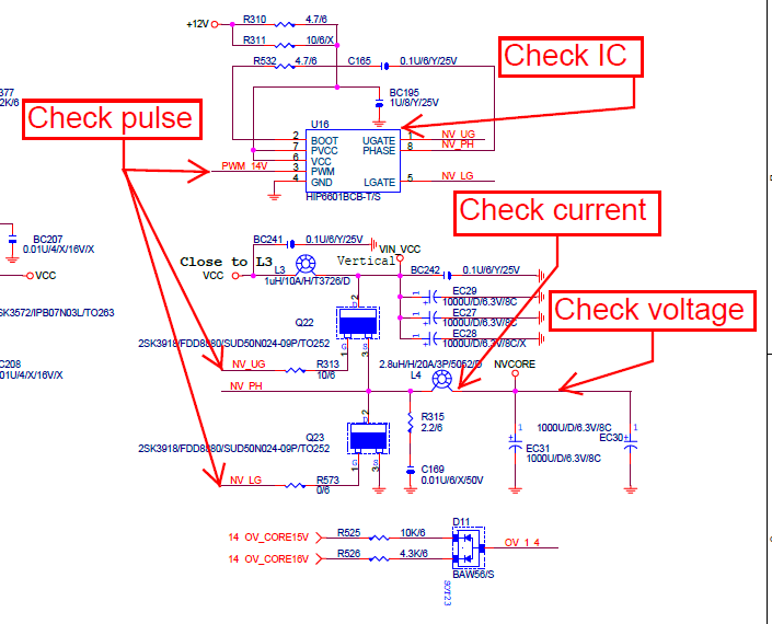
Then i push the power button and the Q23 (MOSFET K3918) starts boiling the welding solder and after a couple of seconds the PSU shuts off imidiatelly.
I measure the resistance between the +12V line and ground and it's only 12 ohms.
I measure the resistance between the +VCC3 line and ground and it's only 15 ohms.
I measure the resistance between the +NVCORE line and ground and it's only 5 ohms.
I took off all the electrolytic capacitors to the above lines. No change in resistance values.
I take off the PCB protection board (in the orange slot), push the power button and then it's open the FAN fully but after about 5-7 sec his speed is going down and keeps runing that way.
Any help would be appreciated
TIA
P.S. I have the circuit diagramm available
I have the mobo GA-8N-SLI-royal and i would like a help.
The problem: I connect the 24 power supply connector, the ATX 12V 4 pins connector, and the 12V/5V 4 pins connector.
I took off the CPU and all the RAM's, I/O cables etc.
The CPU FAN blower in connected.
Then i push the power button and the Q23 (MOSFET K3918) starts boiling the welding solder and after a couple of seconds the PSU shuts off imidiatelly.
I measure the resistance between the +12V line and ground and it's only 12 ohms.
I measure the resistance between the +VCC3 line and ground and it's only 15 ohms.
I measure the resistance between the +NVCORE line and ground and it's only 5 ohms.
I took off all the electrolytic capacitors to the above lines. No change in resistance values.
I take off the PCB protection board (in the orange slot), push the power button and then it's open the FAN fully but after about 5-7 sec his speed is going down and keeps runing that way.
Any help would be appreciated
TIA
P.S. I have the circuit diagramm available