Continue to Site

Welcome to EDAboard.com

Welcome to our site! EDAboard.com is an international Electronics Discussion Forum focused on EDA software, circuits, schematics, books, theory, papers, asic, pld, 8051, DSP, Network, RF, Analog Design, PCB, Service Manuals... and a whole lot more! To participate you need to register. Registration is free. Click here to register now.

6v Lamp battery charger Repair using 13001 transistor

Status
Not open for further replies.

jayaramc

Newbie level 6
Joined
Nov 27, 2011
Messages
14
Helped
0
Reputation
0
Reaction score
0
Trophy points
1,281
Activity points
1,388
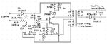
I have a lamp charger using 13001 which is similar to mobile charger and dead recently. I have changed the faulty components 13001 8AV and 8v2 Zener and no other components found to be faulty.

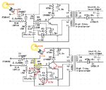
Few detail for your analysis.
Collector to Emitter voltage is 300v. Base to Emitter voltage is 8.2v. The voltage at C4 is 0.5v. All the diodes/resistor/cap and transformer coils are good as well.

I am worried why the transistor is not switching although it has a base voltage of 8v. There is no feedback voltage and secondary output.

I have uploaded a similar circuit.

Kindly help me to get this circuit working.
 

Attachments

  • LightCircuit13001.JPG
    LightCircuit13001.JPG
    54.9 KB · Views: 310

Base to emitter at 8V? Maybe you need a new transistor.
First you need to change C4.
Check/change also R4=15 ohms/ R10= 10 ohms. Check also for a bad solder joint on the emitter to R4 connection path.
 

Thanks for you update.

I have even changed the transistor and i don't see the transistor is open or short. The new transistor also doesn't switch.

I have replaced C4 which didn't help. Also R10 is good and I am able to glow a 60W bulb from collector and emitter of transistor.

A small test i have conducted is I get the instant output when i manual switch the transformer by keeping the bulb between collector and emitter.

Any thoughts please... why the transistor is not switching although it has 8v at base through R7.
 
Last edited:

The fault is *probably* that C5 is open circuit but please be extremely careful when working on this circuit, you are not isolated from the incoming mains power.

My guess is that the 8V at B-E is not a DC voltage but an alternating signal that is confusing your meter.

Brian.
 

I have tried replacing C5 and I am able to successfully discharge it immediately after switch OFF mains, means C5 is working.

Also I am checking in digital meter with DC 1000v option, so obviously I think it should display DC voltage.

I am confused, whether the transistor needs more base voltage... and alter Zener accordingly...
 

Have you check for bad solder joints? Also did you check for any short-circuit in the secondary section?
You may try and change the D1 diode, C1 capacitor…
 

I have already opened D1 from board and connected a LED directly.

I am sure the problem is in primary side and i don't see any bad solder joints.

The transistor is not switching even in 8v means, does it needs more voltage. (I can see the max voltage is 9v for this transistor).

Also is it normal that the voltage across the signalling diode Z1 as 0.5v.
 

Yes, i tried that too adding 1M in parallel.. no luck.. I get 8v at base.
 

If your component are ok and their is no open circuit then your transformer is short circuit internally you need to replace it.
 

I don't think my transformer is faulty, as my earlier test says that I get output when I do a manual switching through a bulb...

My concern is whether 8v is enough to switch this transistor and Z1 voltage of 0.5v is normal.

Now I have tried removing Z2 and Base gets 11v.. but no luck.

Any analysis from you experts will be helpful.
 
Last edited:

You need to protect the circuit by adding a series light bulb (40-60W/230V).

Check also R9. Try to modify R7 down to 220K, this time using a good transistor the light bulb must be turned on...
 

Attachments

  • LightCircuit v2.jpg
    LightCircuit v2.jpg
    206 KB · Views: 174

I have R9 as 100 ohms and R7 as 680K. Before I tried R9 with 10 ohms also... I will check reducing R7 value whether it helps...

Also I have tried removing Z2 and Base gets 11v.. but no luck.

In all aspects the circuit gets DC voltage only and no AC identified after C5.

- - - Updated - - -

You are right. I get 8.2v across Z2 as I use 8v2 and 0.5v across Z1.

I tried adding 280K in parallel across R7 with no effect. To my view the transistor is good, I get ~500ohms across B-E and B-C. T1 and T2 behaves complete -ve and T3 and T4 complete +ve. The bulb glows perfectly between T1/T2 and T3/T4 and not between T3 and T4 which should happen while transistor switching.

- - - Updated - - -

The components that are blown while the circuit is faulty are Z2 and the transistor.

After that I have replaced

Transistor - 13001 8AV
Z2 - 8v2
R5/R9 - 33 ohms
C4 - 220uf / 25v

Items that were checked by

R7 - 680k (added 280k in parallel)
Z1 - 1N4001 (unpinned 1N4001 and added 1N4148)
C5 - verified discharge happens (also tried adding new cap)
R6/R10/D3 - verified bulb is glowing at collector to emitter
Transformer - getting output when manually scratch collector and emitter with bulb.
Transistor - getting ~500ohms across B-E and B-C and tried replacing 2 times.

With all these actions tried already I am not sure what else remains :(
 

I would again say that the meter is giving you a misleading measurement. A DVM will not tell you the truth when measuring in the presence of an AC component and this circuit is a single transistor oscillator so the signal will not be pure DC. If you really have more than 1.2V between base and emitter, according to the data sheet the transistor is in saturation and therefore cannot have 300V across it's C-E pins.

Regarding the transdormer being faulty - it's rare for them to fail but shorted turns in any winding will prevent the circuit oscillating whilst not significantly changing DC conditions.

Brian.
 

@jayaramc
Have you check for the correct orientation of the pins? That’s possible base and emitter pins to be reversed. :-D

- - - Updated - - -

On the other hand, if we look in the datasheet, we may notice that's a very low hfe for the series 13001-8AV (if the ''A'' -> hfe = 10-15)
 
If the oscillation works then I may be getting AC and I don't think the transistor is moving to saturation as I get 300v across B-E although base voltage is 8v.

I have replaced the transistor 13001S 6BD with this 13001 8AV. Does this make any difference here. I am sure on the pins and checked as well... its ECB from printed side.
 

I think
13001S 6BD = 3DD13001S
IC =0.5A
VCEO =400V
P=1W
and
13001 8AV = MJE13001
Collector-base voltage: V(BR)CBO=600V
Collector current: IC=0.2A
And maybe that’s not the perfect replacement for this application.
 
Thanks team.. I do suspect this transistor is not a proper replacement for old one, as it's not switching with Vbe =8v.

Kindly suggest an alternate/equivalent transistor for 13001S 6BD that are available in market. I got only this from the shop when I asked for 13001S.
 

Can anyone suggest me an equivalent for this transistor please, since I don't get 13001S 6BD here.
 

Status
Not open for further replies.

Similar threads

Part and Inventory Search

Welcome to EDABoard.com

Sponsor

Back
Top