Continue to Site

Welcome to EDAboard.com

Welcome to our site! EDAboard.com is an international Electronics Discussion Forum focused on EDA software, circuits, schematics, books, theory, papers, asic, pld, 8051, DSP, Network, RF, Analog Design, PCB, Service Manuals... and a whole lot more! To participate you need to register. Registration is free. Click here to register now.

Input impedance of a half-wave dipole immersed in a dielectric.

Status
Not open for further replies.

DeboraHarry

Full Member level 5
Joined
Dec 3, 2011
Messages
274
Helped
48
Reputation
94
Reaction score
43
Trophy points
1,308
Location
UK
Activity points
3,905
I've tried to simulate using HFSS a thin half-wave dipole which is immersed in a perfect dielectric with Er=81. (This is the same dielectric constant as water, but I used a perfect dielectric for the simulations to get a feel for the results, and to later see how much the conductivity of real water effected the antenna's properties).

I calculated the free space length for the dipole, then shorted it by a factor of sqrt(81)=9. This was then put in a cylinder which had Er=81. The cylinder had a radius of lambda/4 (in the dielectric) around the dipole. The length of the cylinder was lambda. So the dipole was surrounded by dielectric for a quarter wave, where the quarter wave was that in the dielectric - not in air.

An airbox, which surrounded the dielectic by lambda/4 (in air), was put around the dielectric. This was of course much larger than the dielectric, as the wavelength is 9x bigger.

The reasonate frequency calculated in HFSS was close to what I expected. However, at resonance, the real part of the input impedance was only 0.02 Ohms, which is smaller than the free space input impedance by a factor of 3600. (73/0.02=3600). This seems really odd to me.

I changed the point at which HFSS stops refining the mesh so that |S| was 0.01, rather than the default 0.02. I also changed it so there was at least 3 converged passes. This was basically so I could see the result was stable.

What I also did was to ensure the size of the mesh was not more than lambda/6 on both the surfaces of the dielectric and the airbox. The mesh was forced to be much finer (by a factor of 9) on the surface of the dielectric.

Any thoughts what the input Z should be, and if is not 0.02 Ohms, what might be wrong with my HFSS simulation
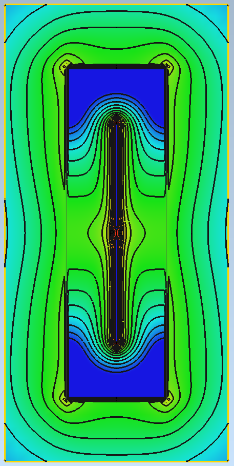
 

There is a strong discontinuity between the fields in dielectric and air. I think that the small Re{Zin} shows that poor radiation.
 

There is a strong discontinuity between the fields in dielectric and air. I think that the small Re{Zin} shows that poor radiation.


But the standard method in HFSS to analyse an antenna is to put it in a box which is lambda/4 away from the antenna - they call it an airbox. Outside the airbox is a perfect electrical conductor.

My antenna is surrounded by a surrounded by the dielectric, then air (well vacuum to be more precise). I accept there will be a large mismatch between air and my dielectirc, but not as much as between air and a perfect conductor. The reflection of a PEC must be higher than that of two dielectrics, even if Er differs by a factor of 81.

I'd be interested if anyone else can simulate this in some software, and what results they get. I do have access to EMPro, but don't know enough about using it, so I'm not able to simulate it.

0.02 + j 0 Ohms just seems an unreasonably low impedance to me.

If a thin film of water (moisture) is on an antenna, it does not dramatically effect the antenna impedance. I think we would agree that if the dielectric extended to infinity, then whilst it will have some effect, there wont be any reflection. So I don't see that effecting the input impedance by a factor of 3600. Perhaps there is some value for the thickness of dielectric, which causes maximum change in input Z, and its neither infinitely thin or infinitely thick.

I'll post my model later, to let others with HFSS have a look at it. I'll also post a screenshot, so others can see what I mean. Perhaps someone with another 3D simulator can have a look at see what they get.

Deborah.
 

But the standard method in HFSS to analyse an antenna is to put it in a box which is lambda/4 away from the antenna - they call it an airbox. Outside the airbox is a perfect electrical conductor.

PEC for sure? Does that make sense?

All 3D solvers that I have worked with use absorbing boundaries for antenna analysis. If the antenna is in air, as usual, then there is some air volume between the antenna and the absorbing boundary. The near field is sampled around the antenna, to do near-field-to-far-field transformation, but still the absorbing boundary is needed to dissipate the radiated energy. I would be very surprised if HFSS uses PEC. An antenna inside a PEC box will show total reflection.

~~

If you give the frequency and dimensions of your antenna, and the dimension and dielectric properties of the dielectric, I can see what I get from "my" 3D solver (Empire XCcell).
 
Last edited:

PEC for sure? Does that make sense?

Yes, you are right. One draws the airbox with PEC on the outside, but I think HFSS "inserts" a radiation boundary there. So whilst it looks like PEC, in fact it is not.

If you give the frequency and dimensions of your antenna, and the dimension and dielectric properties of the dielectric, I can see what I get from "my" 3D solver (Empire XCcell).

Code:
Er = 81, bulk conductivity = 0 (i.e. perfect insulator), relative permeability=1.0 
length of dipole = 1.28 m
radius of dipole = 2 mm
feed gap for dipole = 2 mm
dielectric radius = 587 mm
dielectric length = 2.56 m
frequency 14.0 MHz

The length of the dipole is not quite right for 14.3 MHz, as a quick calculation will show, but I originally based this on a wavelength of 20 m. But try those dimensions, but I know resonance will be a bit below 14 MHz. The value I got for the resonate frequency looked quite reasonable.

If you get anywhere with a reasonable input Z, I'd be interested what happens with distilled water, which according to the material properties in HFSS are:

Er = 81, relative permeability=0.999991, bulk conductivity 0.0002 Siemens/m

These are the results I get:
Code:
Peak directivity 1.4228 (not dB)
Peak gain 1.4192 (not dB)
Peak realized gain (includes mismatch loss) 0.0043741
Radiation efficiency (0.99748) - i.e. over 99%.

At first I thought the peak gain was too high - I expected a large reflection at the air/water boundary. But whilst that is no doubt true, the reflected power will just be be reflected into the dielectric, and some more escape. So it all the power will be radiated, so the efficiency should be 100%.

Of course, if the real part of the input Z is 0.02 Ohms, then it will be practically impossible to implement a matching network that will match this to 50 Ohms. Possibly with access to superconductors it might be!


Deborah
 
Last edited:

If you get anywhere with a reasonable input Z

Like you, I get almost total reflection.

IMO, the transition of the "compressed" field inside the dielectric to the air outside is the problem.
Below is a plot of the E field in the antenna plane (color coding = 40dB log scale).
42_1340799020.png
 

To understand the bad antenna properties, I suggest a different approach. Analyze the dipole in the Er=1 scale, you get an electrical "very" small dipole with a small dielectrical sheet. From this viewpoint the low radiation resistance isn't surprizing.

As a third attempt, consider the antenna plus surrounding dielectric as a resonator, it can achieve a certain impedance transformation effect and a higher radiation resistance (with rather small bandwidth). But not in the present form.

I just tried what you suggested with MMANA-GAL (a NEC2 based software package, not HFSS). The input impedance of a 1.28 m dipole in free space at 14.3 MHz comes out at 0.6 Ohms, so 30 x larger than the dipole of the same physical length immersed in water.

Dave
 

dipole of the same physical length immersed in water.

Actually, what Deborah and myself have analyzed was a dipole embedded in a dielectric tube of finite size (smaller than the wavelength in air), surrounded by air.

What I did not yet understand is the physical setup that Deborah wants to simulate, i.e. if the antenna will be operating "under water", or if the size of the water environment is finite and there is some transition to air in the antenna nearfield.
 

I just tried what you suggested with MMANA-GAL (a NEC2 based software package, not HFSS). The input impedance of a 1.28 m dipole in free space at 14.3 MHz comes out at 0.6 Ohms, so 30 x larger than the dipole of the same physical length immersed in water.
Thanks for showing the limitations of the simplified view. I was primarly commenting the expectation of a getting radiation resistance numbers similar to a regular λ/2 dipole in free space, as in post #3. I think, that the dielectric sheet makes the further difference to your results, partly shorting the field as suggested by the field strength picture.

The more interesting question is how the respective real world antenna structure looks like. But if it's similar to the simulation setup, I assume that the results aren't completely wrong.
 

What I did not yet understand is the physical setup that Deborah wants to simulate, i.e. if the antenna will be operating "under water", or if the size of the water environment is finite and there is some transition to air in the antenna nearfield.

This was an experiment to see if it would be possible to produce a dipole for the 20 m amateur band which is physically smaller than it would be if constructed in the normal way. As such, the amount of water is finite. My plan would be to use the minimum amount of water necessary to reduce the length of the antenna to a managable length. However, as a first guess, I assumed that if the antenna was surrounded by water of about a quarter wave, then it would be sufficient to reduce the length by a significant fraction.

The quarter wave is certainly sufficient to shift the resonate frequency by about a factor of 9, but I was not expecting a fall in the impedance by a factor of 3600.

What did you get as the real part of the input impedance at resonance?

Deborah
 

What did you get as the real part of the input impedance at resonance?

I was using FDTD analysis and there's some numerical precision error from the FFT. The value that I got at 14MHz was -20mOhm, which I would interpret as "very close to zero".


This was an experiment to see if it would be possible to produce a dipole for the 20 m amateur band which is physically smaller than it would be if constructed in the normal way.

Seems like my interpretations from post #7 hit the point better than I could expect.

I'm under the impression that the design shares the general drawbacks of electrical small antennas and add some specific ones.
 

Status
Not open for further replies.

Part and Inventory Search

Welcome to EDABoard.com

Sponsor

Back
Top