Continue to Site

Welcome to EDAboard.com

Welcome to our site! EDAboard.com is an international Electronics Discussion Forum focused on EDA software, circuits, schematics, books, theory, papers, asic, pld, 8051, DSP, Network, RF, Analog Design, PCB, Service Manuals... and a whole lot more! To participate you need to register. Registration is free. Click here to register now.

Confusion regarding synchronous inputs

Status
Not open for further replies.

Pranto

Newbie level 3
Joined
Jun 22, 2012
Messages
4
Helped
0
Reputation
0
Reaction score
0
Trophy points
1,281
Activity points
1,308
I have the following question for my fellow circuit enthusiasts..
It might seem like a very stupid question(it might be actually stupid)

I am confused with the following circuit.
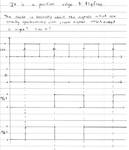
It's a simple D flipflop. It's D input changes at the clock edge. What should be the output? Confused due to setup time violations
I tried simulations in Xilinx ISE and got output as o/p2 in the image.

I am attaching this image to illustrate my problem.
Untitled.png

Please help.
 

Dear Pranto
Hi
They are correct but one of the out puts is inverted instead of the other one . see your inverted waveform ( end of your page , right section ) this section has problem .
Best Wishes
Goldsmith
 
Last edited:

Dear Pranto
Hi
They are correct but one of the out puts is inverted instead of the other one . see your inverted waveform ( end of your page , right section ) this section has problem .
Best Wishes
Goldsmith

- - - Updated - - -

Dear Pranto
Hi
They are correct but one of the out puts is inverted instead of the other one . see your inverted waveform ( end of your page , right section ) this section has problem .
Best Wishes
Goldsmith

I didn't get you Sir. My question was which output is right? o/p1 or o/p2 ?
I didn't understand the inverted part as well.
 

Humm ! as you probably know each D flip flop has two out put . first one is in phase and the other one is out of phase ( 180 degree ) . ok ?
 

Oh yes so u mean Q and Qbar. O/p 2 in the image is not Qbar.

I meant to show two solutions i.e. two Q outputs and wanted to know which one is right.

Sorry for the confusion.
 

The result from such a simulation is not very interesting. The important thing here is that the real circuit will be unpredictable if you violate the setup/hold timing.
You can get the first or the second result, or the problematic metastable behavior.
 

There are circuits which have signals synchronous with clock signal. The main question I had was regarding such a circuit where
the signals are generated on the clock edge. For simplification I regarded the ckt as a D flip flop.

Based on my understanding the o/p1 is more probable case due to setup time requirements and nearly zero hold time requirement
in modern circuits.But I dont have any concrete source for it.
 

Status
Not open for further replies.

Part and Inventory Search

Welcome to EDABoard.com

Sponsor

Back
Top