powersys
Advanced Member level 1
I have two 3-phase inverters. One is from Semikron (with IGBTs, rated 600V, denoted as Semikron-Inverter in this post). Another one is a home-made prototype.
The schematic of the home-made prototype inverter is shown in Figure 1, while its physical layout is shown in Figure 2. The specifications of the power switches used in the home-made prototype inverter (HMP-Inverter) are as the following:
IRFP4310ZPbF (power MOSFET)
VDSS: 100V
RDSon: 6mΩ
ID: 130A
VGS: ±20V
http://www.irf.com/product-info/datasheets/data/irfp4310zpbf.pdf
Each HMP-Inverter leg is driven by a IR2110 (manufactured by International Rectifier).
http://www.irf.com/product-info/datasheets/data/ir2110.pdf
More than 10pcs of IRFP4310ZPbF were killed so far and all of them were from leg-C (see Figures 1 and 2). I wish to find out the reasons that kill the IRFP4310ZPbF and why the damage was always at leg-C. When checked with multimeter (using the 'continuity' feature), the G, D, S pins of damaged IRFP4310ZPbF were found shorted. I do not know whether the failures were caused by overvoltage or overcurrent.
Then, the Semikron-Inverter was used to drive the same motor (with the same DSP controller and control algorithm). Please note that the DC-link voltage of the inverter is supplied by a Xantrex power supply (100V/50A), which has a digital display showing the supplied voltage and current. Sometimes the voltage shown on the Xantrex power supply (PSU) display fluctuated (decreased and increased). Occasionally, the fluctuation triggered the overvoltage protection (OVP) of the Xantrex PSU (the OVP of the PSU is set at 115V). It looks to me that the back-emf of the motor, due to some unknown reasons, was "added" to the DC-link voltage and when the effective DC-link voltage was higher than 115V the OVP of the PSU was triggered.
So, my guess is the damaged IRFP4310ZPbFs in HMP-Inverter were probably caused by overvoltage. When HMP-Inverter was used with the Xantrex PSU, the OVP of the PSU was never triggered. Since IRFP4310ZPbF is rated at 100V, the overvoltage (slightly above 100V) would have killed the power MOSFET first before it reached the 115V OVP limit of the Xantrex PSU.
My another guess on why the damages were always at leg-C is that, as shown in Figure 2, the power MOSFETs of leg-C were placed closer to the DC-link. Do you think this reason make sense?
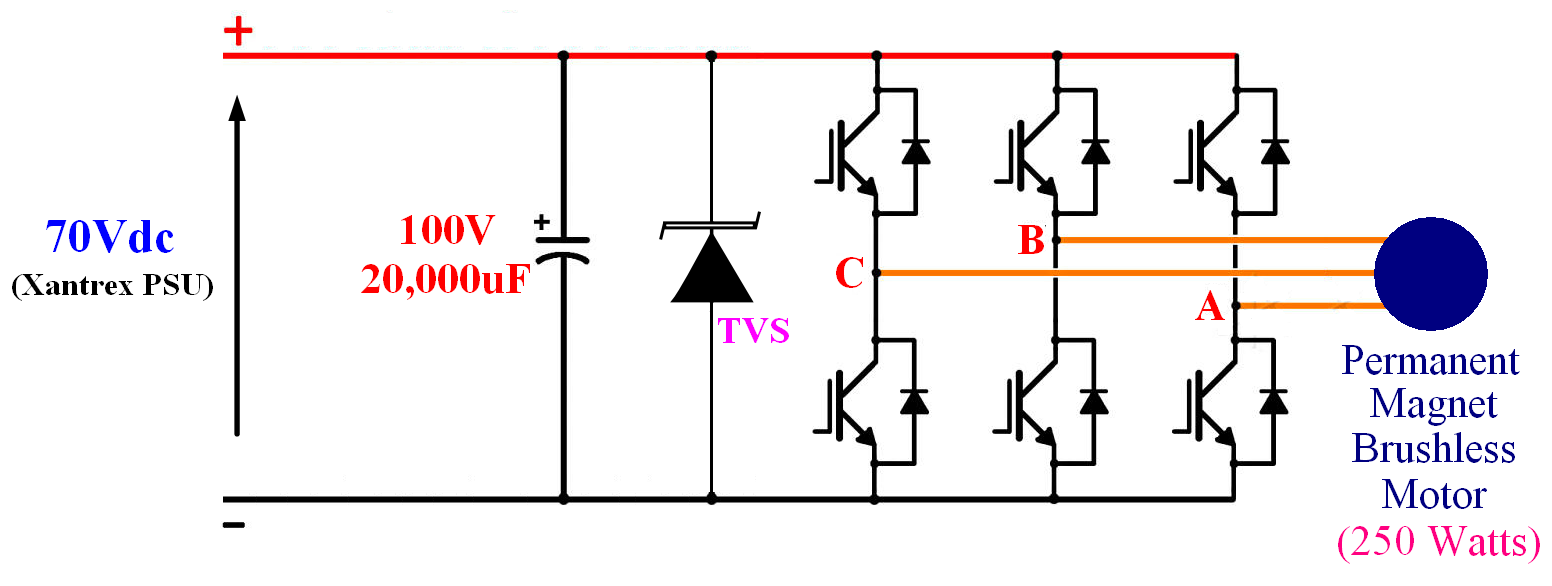
By the way, if a TVS or transorb (rated below 100V) is added to the inverter as shown in Figure 3, can the power MOSFETs be protected from overvoltage?
Thanks.
Figure 1: Inverter schematic.
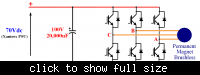
Figure 2: Physical layout of the inverter (viewed from the top). Gate drive circuit is not shown.
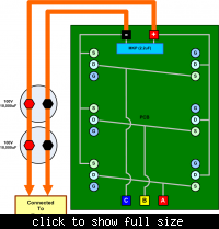
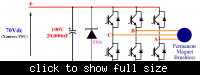
Figure 3: Inverter with a TVS or transorb.
Pim: Generally speaking, power MOSFETs can withstand over-current better than one can believe, but over-voltage is an instant killer...
https://www.edaboard.com/threads/224099/#post955299
spiba: I fully agree with you that 90 % of the mosfets are damaged due to Overvoltage rather than overcurrent...
https://www.edaboard.com/threads/224099/#post955617
richie: MOSFETs have very little tolerance to overvoltage. Damage to devices may result even if the voltage rating is exceeded for as little as a few nanoseconds. MOSFET devices should be rated conservatively for the anticipated voltage levels, and careful attention should be paid to suppressing any voltage spikes or ringing.
http://www.richieburnett.co.uk/mosfail.html
FvM: A serious problem arises however from the fact, that the bulk diodes are forward biased, sourcing high reverse current to the battery...
https://www.edaboard.com/threads/224099/#post956575
FvM: You should analyze more thoroughly what happens in the circuit. Did you undertstand the bulk diode conduction problem? It can't be handled by a inverter shut-down, you have to disconnect the battery, respectively allow the transformer center tap to rise to about 40V.
https://www.edaboard.com/threads/224099/#post956885
The schematic of the home-made prototype inverter is shown in Figure 1, while its physical layout is shown in Figure 2. The specifications of the power switches used in the home-made prototype inverter (HMP-Inverter) are as the following:
IRFP4310ZPbF (power MOSFET)
VDSS: 100V
RDSon: 6mΩ
ID: 130A
VGS: ±20V
http://www.irf.com/product-info/datasheets/data/irfp4310zpbf.pdf
Each HMP-Inverter leg is driven by a IR2110 (manufactured by International Rectifier).
http://www.irf.com/product-info/datasheets/data/ir2110.pdf
More than 10pcs of IRFP4310ZPbF were killed so far and all of them were from leg-C (see Figures 1 and 2). I wish to find out the reasons that kill the IRFP4310ZPbF and why the damage was always at leg-C. When checked with multimeter (using the 'continuity' feature), the G, D, S pins of damaged IRFP4310ZPbF were found shorted. I do not know whether the failures were caused by overvoltage or overcurrent.
Then, the Semikron-Inverter was used to drive the same motor (with the same DSP controller and control algorithm). Please note that the DC-link voltage of the inverter is supplied by a Xantrex power supply (100V/50A), which has a digital display showing the supplied voltage and current. Sometimes the voltage shown on the Xantrex power supply (PSU) display fluctuated (decreased and increased). Occasionally, the fluctuation triggered the overvoltage protection (OVP) of the Xantrex PSU (the OVP of the PSU is set at 115V). It looks to me that the back-emf of the motor, due to some unknown reasons, was "added" to the DC-link voltage and when the effective DC-link voltage was higher than 115V the OVP of the PSU was triggered.
So, my guess is the damaged IRFP4310ZPbFs in HMP-Inverter were probably caused by overvoltage. When HMP-Inverter was used with the Xantrex PSU, the OVP of the PSU was never triggered. Since IRFP4310ZPbF is rated at 100V, the overvoltage (slightly above 100V) would have killed the power MOSFET first before it reached the 115V OVP limit of the Xantrex PSU.
My another guess on why the damages were always at leg-C is that, as shown in Figure 2, the power MOSFETs of leg-C were placed closer to the DC-link. Do you think this reason make sense?
By the way, if a TVS or transorb (rated below 100V) is added to the inverter as shown in Figure 3, can the power MOSFETs be protected from overvoltage?
Thanks.
Figure 1: Inverter schematic.
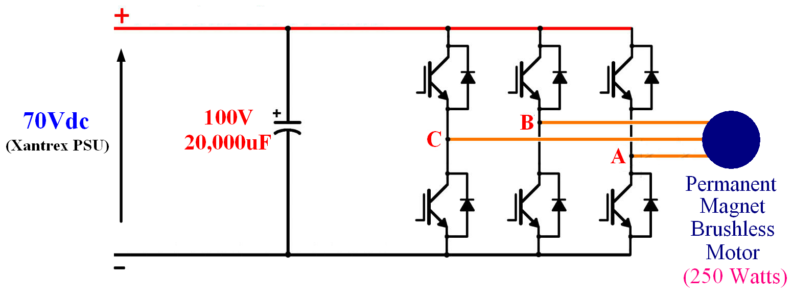
Figure 2: Physical layout of the inverter (viewed from the top). Gate drive circuit is not shown.
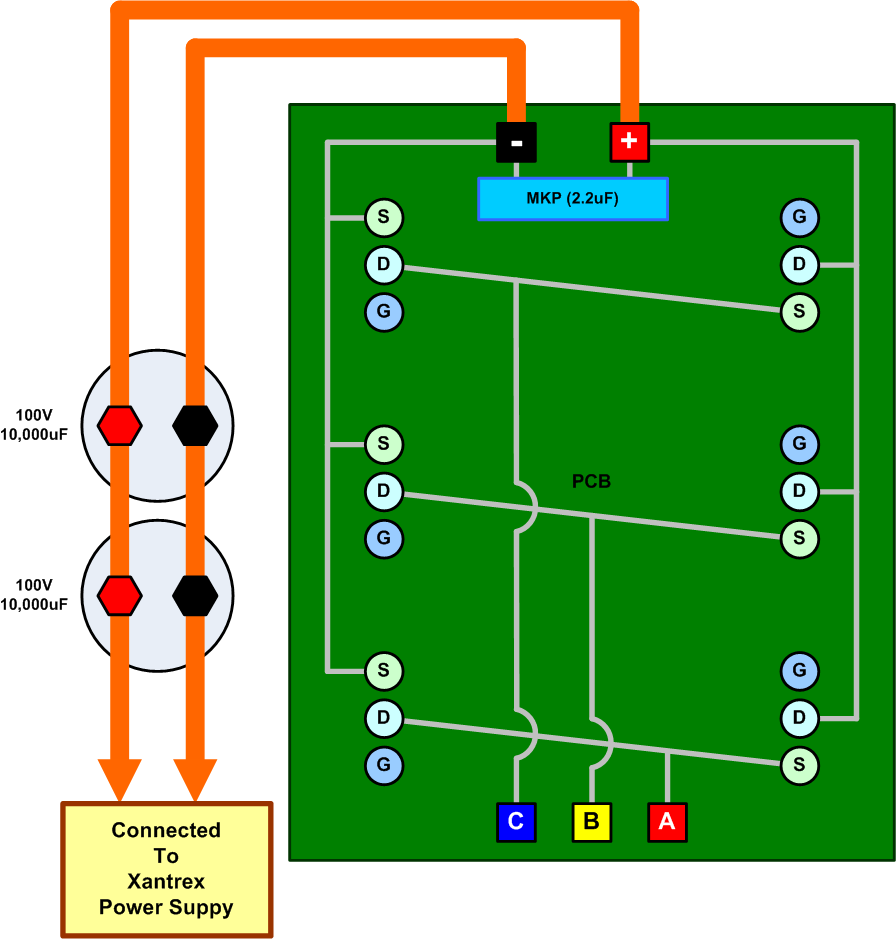
Figure 3: Inverter with a TVS or transorb.
Pim: Generally speaking, power MOSFETs can withstand over-current better than one can believe, but over-voltage is an instant killer...
https://www.edaboard.com/threads/224099/#post955299
spiba: I fully agree with you that 90 % of the mosfets are damaged due to Overvoltage rather than overcurrent...
https://www.edaboard.com/threads/224099/#post955617
richie: MOSFETs have very little tolerance to overvoltage. Damage to devices may result even if the voltage rating is exceeded for as little as a few nanoseconds. MOSFET devices should be rated conservatively for the anticipated voltage levels, and careful attention should be paid to suppressing any voltage spikes or ringing.
http://www.richieburnett.co.uk/mosfail.html
FvM: A serious problem arises however from the fact, that the bulk diodes are forward biased, sourcing high reverse current to the battery...
https://www.edaboard.com/threads/224099/#post956575
FvM: You should analyze more thoroughly what happens in the circuit. Did you undertstand the bulk diode conduction problem? It can't be handled by a inverter shut-down, you have to disconnect the battery, respectively allow the transformer center tap to rise to about 40V.
https://www.edaboard.com/threads/224099/#post956885
Attachments
Last edited: