Continue to Site

Welcome to EDAboard.com

Welcome to our site! EDAboard.com is an international Electronics Discussion Forum focused on EDA software, circuits, schematics, books, theory, papers, asic, pld, 8051, DSP, Network, RF, Analog Design, PCB, Service Manuals... and a whole lot more! To participate you need to register. Registration is free. Click here to register now.

Altium designer 6 - Slotted Pad image on Mech 1

Status
Not open for further replies.

Petethered

Newbie level 3
Joined
Jun 2, 2012
Messages
4
Helped
0
Reputation
0
Reaction score
0
Trophy points
1,281
Activity points
1,319
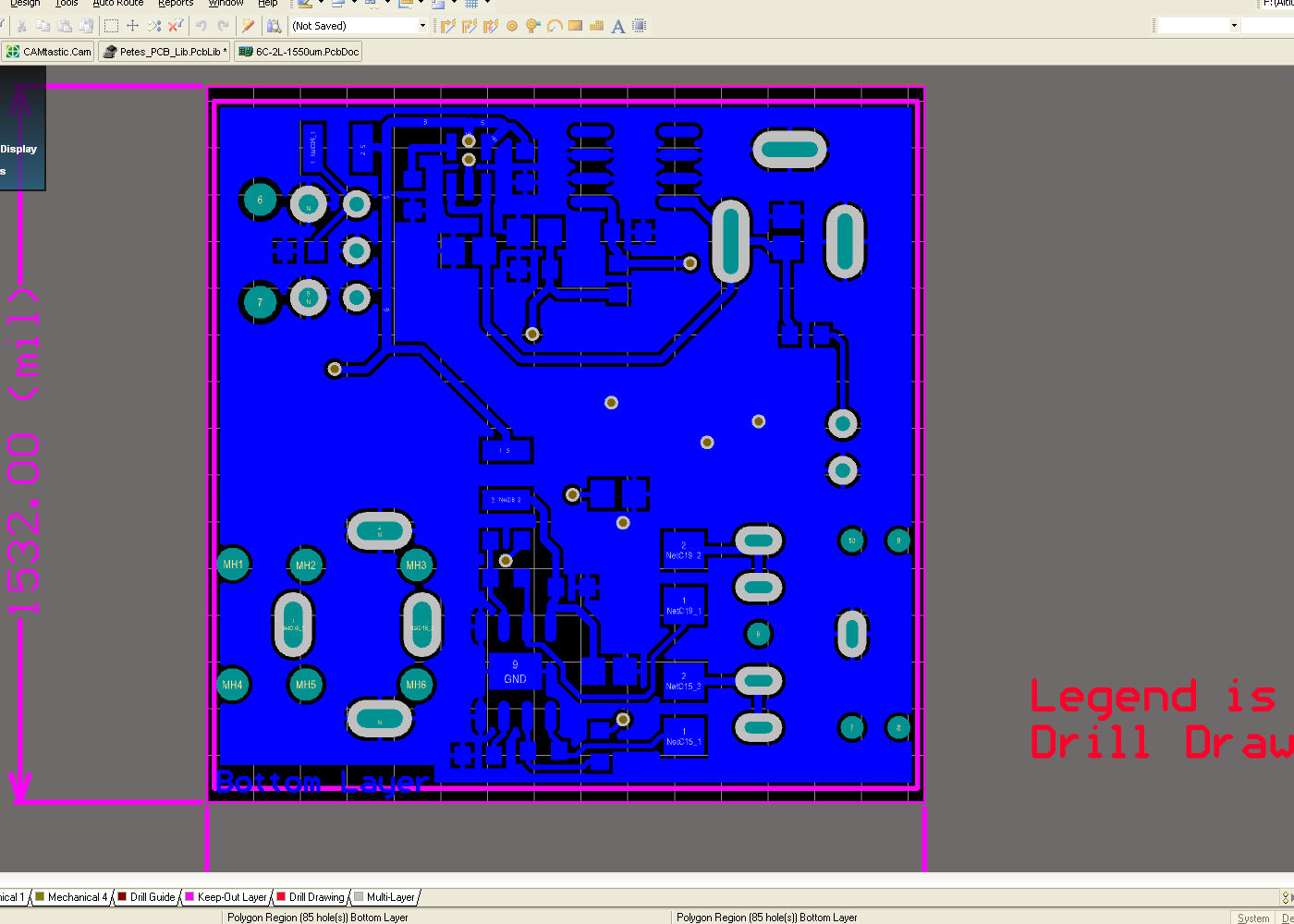
I have three different PCB footprints on my board each with slotted through plated pads.
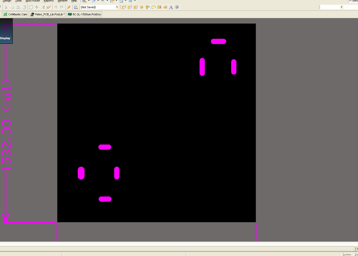
Two of the footprints show the slot holes on Mech layer 1, but one does not.

I believe the two showing the slots, I modified from existing library footprints and the last I created from scratch. (Changing hole from round to slot and changing pad size and shape).

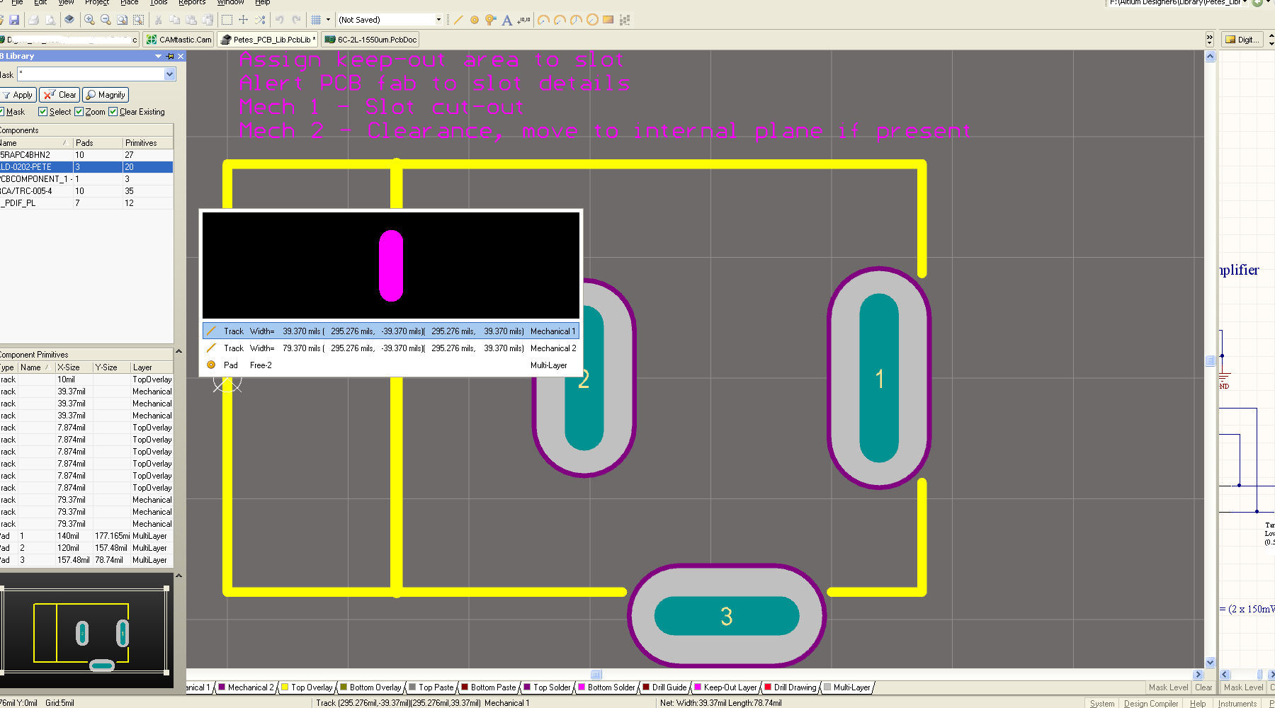
If I select the (correct) individual slotted pad they show :-

- The pad.
- Mech layer 1 : Slot definition.
- Mech layer 2 : Pad definition.

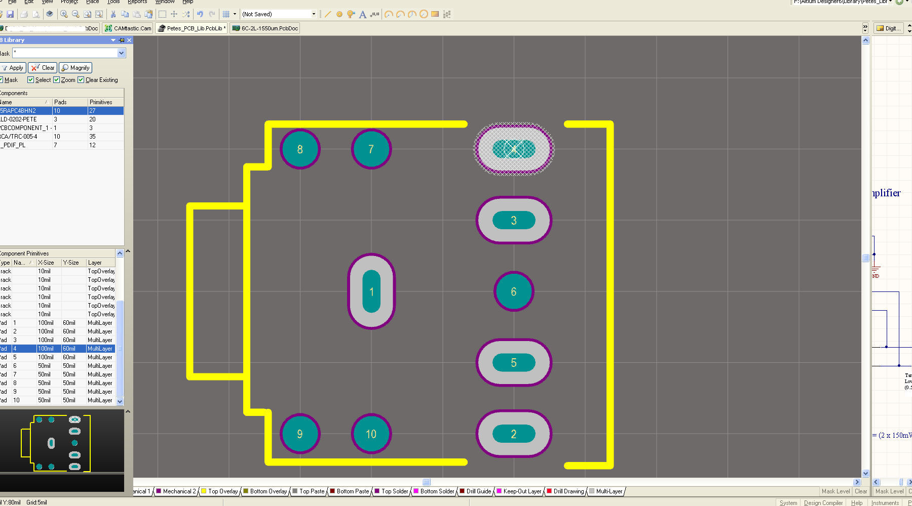
If I select the pads on the footprint I created, it only selects the pad - no Mech 1 slot definition.

Is there a special string or a rule I need to setup to show the slot on Mech 1?
 

is the slot represented with tracks and arcs on that specific layer?
Maybe you can double check when you are in single layer mode?
 

The slots are represented with tracks of the correct thickness and length on Mechanical Layer 1 - on two of the components but not the third.
Looking at Drill drawing the slots for all the components are listed correctly.
I am defininetly not in single layer mode.
 

I have attached 3 .jpg's showing :

- The footpint with the slot info on Mech1, clicking on the pad shows the pad & mech info.
- The footprint without slot info on Mech 1, clicking on the pad just shows the pad.
- The bottom layout showing the three footprints with slots.
- Mechanical layer1 showing only two footprints with slot info.


in the first picture, it seems that you have 2 tracks and one pin on top of each other.
try and delete those tracks on mech1.
 

The Altium footprints I modified have the 2 tracks on the pads :-

1 on Mechanical layer 1 to notify the manufacturer of the slots.
1 on Mech layer 2 for clearance (not sure of the purpose).

When I modified the slot widths and lengths on the pad the Mech 1 & 2 tracks changed aswell which is ideal.
I can delete the tracks but I want the manufacturer to see the slot info on Mech 1.

The footpint 'I' created only has the slotted pads and no tracks on Mech 1 or 2 and I don't know why.

- - - Updated - - -

The Altium footprints I modified have the 2 tracks on the pads :-

1 on Mechanical layer 1 to notify the manufacturer of the slots.
1 on Mech layer 2 for clearance (not sure of the purpose).

When I modified the slot widths and lengths on the pad the Mech 1 & 2 tracks changed aswell which is ideal.
I can delete the tracks but I want the manufacturer to see the slot info on Mech 1.

The footpint 'I' created only has the slotted pads and no tracks on Mech 1 or 2 and I don't know why.
 

If you need them, can't you simply add them to your footprint? Track width is 40 mils wider from Mech 1 and to Mech 2 in your picture.
 

Yes as loosemoose has said you can also add them to your footprint or you can also add them in layout file at the pad locations.
 

Status
Not open for further replies.

Part and Inventory Search

Welcome to EDABoard.com

Sponsor

Back
Top