Continue to Site

Welcome to EDAboard.com

Welcome to our site! EDAboard.com is an international Electronics Discussion Forum focused on EDA software, circuits, schematics, books, theory, papers, asic, pld, 8051, DSP, Network, RF, Analog Design, PCB, Service Manuals... and a whole lot more! To participate you need to register. Registration is free. Click here to register now.

Need help with TRIAC and photo-triac connection to MicroController Please

Status
Not open for further replies.

rallysteve

Newbie level 6
Joined
Apr 24, 2012
Messages
14
Helped
0
Reputation
0
Reaction score
0
Trophy points
1,281
Activity points
1,417
Hi there, I am just finishing off my Micro-Controlled Light Dimmer system. However I am struggling to work out component values and connections for my Triac and Photo Triac.

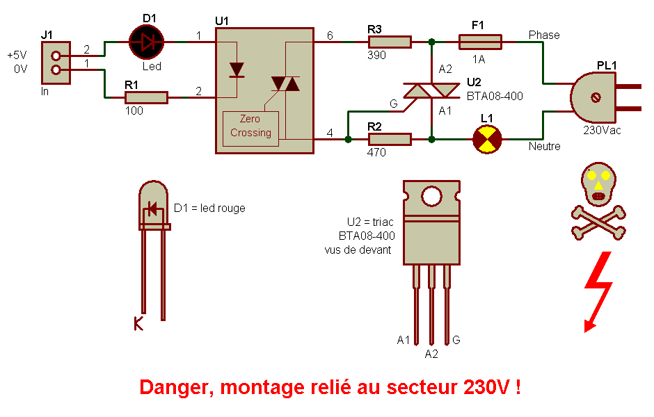
I have a 5v pulse from my micro-controller to swich a triac at a varying point every half cycle. This will be connected to a photo-triac to isolate from AC, I have Vishay IL-420 for this. The triac I have to use with the system is a TIC225M. I realise that I need to use a 'snubbing circuit' and provide the correct gate current at the triac but I am struggling to work out what component values and connections to make. I dont want to mess up with mains voltage.
I am going to be operating a single 40W light bulb on 230V mains (UK) as this is only a prototype.

Can anyone help at all please?

Thanks
Steve
 

Dear Steve
Hi
Can you attach the schematic that you're working on ? thus i can help you as well as possible .
Best Wishes
Goldsmith
 

Hi GoldSmith, Thanks for your help, the schematic I have attached below (apologies for the hand drawing I have not got my CAD program with me!) I can interface the IL420 to my microcontroller with a single 270 Ohm resistor I belive which will not damage the uC but provide enough current to drive the IL420 Photo-triac. It is the part between the IL-420 and Triac I am unsure about if you can help please. In the schematic below I think R2 and C1 form the "Snubbing".

Thanks
Steve
**broken link removed**
 

Hi Steve
The resistor between your opto triac and micro controller , will calculate by : ( if the supply of your micro is about 5 volt )
5-1.35/10*10^-3
( as i saw in it's datasheet it's forward voltage will be 1.35 v ) . so it's value will be about = 365 ohms ( it will be the best value for it .) .
And about C1 , i think it isn't necessary because your voltage is AC . so just R1 is enough . and about snubber network , it should be a series RC network that is in parallel with Mt1Mt2 . it should correct the behavior of triac instead of inductive loads .
I hope my answer could help you .
Best Wishes
Goldsmith
 

Many Thanks Goldsmith. I will have another look and get back to you if I have any more problems.

Thanks
Steve
 

Consider the 40W bulb as 400W on cold startup so R-Load is around 1.5 Ω cold or 8x more current that test load.

Specs are showing 20mA worst case at 10Ω load @-40'C and ~ 8mA @20'C
So consider 8x more current or 32 ~ 160mA @-40'C
This is result of pulse from Diac RC discharge circuit.

Report on working values when done.
 
Last edited:

Hi there,
How about the zero-x optotriac,
electronique_interface_230V_001.gif


which one can be used for PWM to dim the lamps?

and, is this true: relays can't be used for PWM purposes, meaning the controlling pulses from uC (1-100% duty cycle )to the relay.

Thanks for clarifying

Wad
 

Dear Wad
Hi
PWM ? if you want to use PWM , you have to use a chopper ( with another triac and an RC network ) to turn off your triac in your desired time .
And about the circuit that you showed , i think it isn't reasonable , because of dissipation across those low value resistors , why that way ? why not a simple resistor from MT2 to the gate ?
Best Wishes
Goldsmith
 

These days if you don't have the experience simply use an integrated Optical Switch or pref. name is "Solid State Relay". They come intimate with all the varieties with safety features, dimmer, remote control, various loads, DC/AC load, timers, EMI control. So get familiar with all of the characteristics of an excellent SSR (thousands of p/n's) before trying to design one. Look at transfer gain margin over temp as a critical spec. See end of this note.

Also consider dimmable controllers for newer technology such as tri-phosphor tubes and LED's because Halogen and Edison tungsten bulbs are swiftly being migrated into the task heating lamp section. ;)

If you really wanted to use PWM on AC, consider converting to DC then PWM on DC or use direct switching on non-inductive loads using IGBT's, G*d's gift to engineers who shall demand high voltage & currents with low switch saturation voltages for big jobs with big budgets. Such as this tiny device <$5 rated for 1000V, 80A.
But seriously, to turn on a light bulb, we used 1:1 windings irons on a core as "pulse transformers" in the 60's to drive triacs to light bulbs with pulses from chips, even zero crossing pulses generated from CMOS.

That's old hat for hobbiests, but pro's will use certified "Solid State Relays" (SSR) which are usually optically isolated SCR's or Triacs or.. . they will choose discrete parts carefully to cover every possible risk of failure and environmental range requirement. I have taken liberty to choose a 2A SSR for you here. with datasheets there too or here which are plastic like SCR's with 4 leads for $4.27/pc or $2 in vol. or this one with ZCS and snubber rated @6A 400 or 600V
 
Last edited:

Steve didn't mention PWM at all, thus I don't understand what the discussion is about. PWM isn't a very specific term, some people may use it for phase angle control or full wave switching with variable number of cycles as well. In case of a lamp load, I would expect phase angle control.

The circuit in your hand sketched schematic is well corresponding to manufacturer suggestions and in my opinion better than the circuit in post #7. If I understand right, you are mainly asking for the RC component values. To tell the result without lengthy discussion, I have been often using two 220 ohm (0.5 W) resistors and a 47 nF (250 VAC) capacitor.
 

Right it was WAD who suggested PWM .... Screen shot 2012-05-14 at 2.48.03 PM.PNG
SSR simple solution;

- with Zero Cross switching & snubbing
- without ZCS but with linear dimming
- wide range of inputs or outputs and save on PWB for simple use.

Note that if you intend to protect the AC circuit from false trigger spikes from the line causing a follow-on switching of power for up to end of cycle, pay close attention to symbol of surge suppressor in my schematic above across output of SSR triac. In case of noise from near lightning surges , cross-over switches etc. this is a safety device in addition to the RC snubber which attenuates most little transients. Your Power Meter only offers arc suppression at 6KV outside the home. This is done with a 6mm gap. It is also noteworthy that it may be costly to protect for all consumer products, so you often find they are protected to 1.5kV or 3kV only, when 6kV transients are possible. from nearby surges, not direct hits. Traditional solutions are MOV's that cost $0.25 and are good for a dozen surges before going open circuit.
 
Last edited:

Status
Not open for further replies.

Part and Inventory Search

Welcome to EDABoard.com

Sponsor

Back
Top