Continue to Site

Welcome to EDAboard.com

Welcome to our site! EDAboard.com is an international Electronics Discussion Forum focused on EDA software, circuits, schematics, books, theory, papers, asic, pld, 8051, DSP, Network, RF, Analog Design, PCB, Service Manuals... and a whole lot more! To participate you need to register. Registration is free. Click here to register now.

How can I convert a square wave output to a nearly sine wave output?

Status
Not open for further replies.

baghu

Newbie level 6
Joined
Mar 10, 2012
Messages
12
Helped
0
Reputation
0
Reaction score
0
Trophy points
1,281
Activity points
1,388
I have this board for generating square waves:

https://circuitsdiy.com/inverter-oscillator-board-using-flip-flops-74ls112


I want to convert this square wave output of the oscillator to a nearly sinewave output without much hassle. I want to feed the near sinewave output to an audio amplifier and then the output of the amplifier to a 12V to 220V-24watts step up transformer. My load will be around 220V, 10-12 watts but it needs near sinewave like that from the output of an APC UPS. Squarewaves don't drive it. (The load is a vibration based air-pump.). Please help me. Thanks. :smile:

EDIT: The frequency is 50 Hertz.
 

Dear baghu
Hi
You'll have many ways , such as twin integrator , or filtering . but i thing you are at improper way .
You can use an SG3526N for all of your things , or you can use an SPWM and link inverter ( to obtain , Best sine wave .)
Best Things
Goldsmith
 

You need a filter that has a frequency cut off that falls between the first and second harmonic of your wave. Put simply you need a filter with a cut off frequency of between the speed of your square wave and double the speed of your square wave, you could do this with a simple CR network set up for a low pass filter, provided you dont need too much power at the output. By having a filter with the cutoff in this place all frequencies that make up your square wave barring the main sine wave of the signal will be removed.

Hope this helps.

/Pheetuz
 

Thank you so much Mr. Pheetuz and Mr. Goldsmith. May I ask something? What will happen if I add two inductors in series and a non-polarized capacitor in parallel with the output of the square wave? Will this work?
 

Again Hi
Yes it will work , but you'll have use large value of inductor and capacitor that isn't economical if your frequency is low ( e.g 50HZ ) .

Wish you the best
Goldsmith
 

Hi,

Thank you Mr. Goldsmith for your prompt reply. Can you kindly suggest me the approximate values of the inductor and capacitor for this project? Will this output an almost pure sinewave?
 

No problem .
But you should tell the value of your out put current and out put voltage and the frequency of your square wave , and the number of harmonic that you want and your out put impedance ( your minimum load and maximum load .
Respect
Goldsmith
 

No problem .
But you should tell the value of your out put current and out put voltage and the frequency of your square wave , and the number of harmonic that you want and your out put impedance ( your minimum load and maximum load .
Respect
Goldsmith

Thanks so much sir for your concern. The square wave frequency is 50 Hz. I want a step approximation sine wave like the output of APC branded UPS. The load is a electromagnetic vibration based air pump. It is rated 8watts at 220 volts. Impedance of the vibrator's coil is 6180 ohms at 35degree C. There would not be a no load condition as the machine will be always connected to it.

Don't know the impedance of the transformer though. I am yet to buy one. I am planning to buy a 220v to 12v 2Amp step down transformer and connect it in reverse windings.
Many thanks and regards,
Baghu.
 

I am planning to buy a 220v to 12v 2Amp step down transformer and connect it in reverse windings.

Again Hi baghu

Again i have to say , that it is not good way . but if you decided to do it , no problem .
Well , how did you measure the impedance of that ? ( when your inverter hasn't feed back from out put voltage , it is important to know the exact impedance ambient . because , as we know the LC filter that you want to use , will be low pass filter , that consist L and C , and the response of this arrangement will influence of load impedance .)
( If your load impedance become higher than the out put impedance of filter , the out put voltage can increase ( very higher than input voltage !) is it attractive ?!!
And if the impedance of load become lower than the out put impedance of your filter , thus , the out put voltage will decrease , simply ! )
So be sure about your impedance and again tell me it's clear value .
Best Wishes
Goldsmith
 
  • Like
Reactions: baghu

    baghu

    Points: 2
    Helpful Answer Positive Rating
I think I was wrong at that time. I got the value of impedance from user manual. But I have measured it just now.


I don't know how this happens. I pulled out the vibrator from the plug and measured the resistance of the two coils which are in parallel, individually. I did it with a multimeter. Each has a resistance of 2.89K while hot (operating temp 40C to 45C) and 2.86K while cold. But this translates to 16+16=32 watts! How can it be rated 8watts?
 

Did you measure it's impedance with multimeter , really ?!
No , it isn't , the way !
I didn't say , resistance ! you measured the resistance !
Do you know about meaning of impedance ? If yes , no problem , but if no :
The impedance , Is the stand due to the AC signal ! You should measure it's inductance with LCR meter , or the catalog of your thing . and then : XL= 2*pi*F*L or omega*L .
So as you told , F=50HZ , and pi =3.14 ( approximately ).
And 2 is a constant . and you measured the L value instead of henry .
Try this way.
Good luck
Goldsmith
 
  • Like
Reactions: baghu

    baghu

    Points: 2
    Helpful Answer Positive Rating
You can get by with a single coil. It will cause current to rise or fall gradually in response to voltage reversals. This produces a sine wave.

As to what value coil...

You want the coil to reach equilibrium just before each voltage reversal takes place. To reach equilibrium takes about 5 time constants. There is .01 second between voltage reversals. So you want a time constant of .002.

The TC formula for inductance is L / R.

Or, L = R * TC.

Thus if your loop impedance is 50 ohms, then your coil should be 100 mH.

If loop impedance is 100 ohms, then your coil should be 200 mH.

If loop impedance is 200 ohms, then your coil should be 400 mH.

Etc.

If the transformer were to be of the right henry value, then it may provide sufficient filtering by itself. However the extra coil will still be of use to reduce buzzing in the transformer.

---------- Post added at 20:39 ---------- Previous post was at 19:46 ----------

Edit:

I'm sorry, a single coil won't give you a sine wave. More like a lopsided triangle wave. I'll see what adding a capacitor can do.

I still don't believe you absolutely need two coils.

---------- Post added at 22:09 ---------- Previous post was at 20:39 ----------

Yes, adding a capacitor is sufficient to give an approximation of a sine wave.

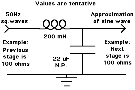
This is the layout I come up with. Values are only tentative. The waveform can be improved by some experimentation.

15_1331521714.gif
 

Did you measure it's impedance with multimeter , really ?!
No , it isn't , the way !
I didn't say , resistance ! you measured the resistance !
Do you know about meaning of impedance ? If yes , no problem , but if no :
The impedance , Is the stand due to the AC signal ! You should measure it's inductance with LCR meter , or the catalog of your thing . and then : XL= 2*pi*F*L or omega*L .
So as you told , F=50HZ , and pi =3.14 ( approximately ).
And 2 is a constant . and you measured the L value instead of henry .
Try this way.
Good luck
Goldsmith
Hi,
I am really sorry Ali. I don't have a LC meter to measure the inductance. Is there any other way to do so? Thanks.

---------- Post added at 23:39 ---------- Previous post was at 23:28 ----------

You can get by with a single coil. It will cause current to rise or fall gradually in response to voltage reversals. This produces a sine wave.

As to what value coil...

You want the coil to reach equilibrium just before each voltage reversal takes place. To reach equilibrium takes about 5 time constants. There is .01 second between voltage reversals. So you want a time constant of .002.

The TC formula for inductance is L / R.

Or, L = R * TC.

Thus if your loop impedance is 50 ohms, then your coil should be 100 mH.

If loop impedance is 100 ohms, then your coil should be 200 mH.

If loop impedance is 200 ohms, then your coil should be 400 mH.

Etc.

If the transformer were to be of the right henry value, then it may provide sufficient filtering by itself. However the extra coil will still be of use to reduce buzzing in the transformer.

---------- Post added at 20:39 ---------- Previous post was at 19:46 ----------

Edit:

I'm sorry, a single coil won't give you a sine wave. More like a lopsided triangle wave. I'll see what adding a capacitor can do.

I still don't believe you absolutely need two coils.

---------- Post added at 22:09 ---------- Previous post was at 20:39 ----------

Yes, adding a capacitor is sufficient to give an approximation of a sine wave.

This is the layout I come up with. Values are only tentative. The waveform can be improved by some experimentation.

15_1331521714.gif

I got the idea. Thanks so much. If I add a large value capacitor in parlallel then a sinewave is produced. Is 22microfarad sufficient for my purpose to increase efficiency and reduce the humming? Thank you.
 

The coil and cap values give a reasonable sine wave at 50 Hz and the indicated input and output impedances. I used ballpark figures in my simulator.

Both the coil and capacitor must be selected for 50 Hz, combined with the overall loop impedance. We cannot easily calculate the impedance. As Goldsmith points out, the impedance is resistance plus reactance. It's not easy to measure. It must be done while the circuit is operating.

Hence experimentation is required. As to changing capacitors, this is easy. The coil is not so easy.

>>>> The important point to notice is that the smaller your incoming impedance, the larger the henry value the coil needs to be.

Also unknown is what is the impedance of the following stage. If this is high, then you must attach a resistive load, to provide a current path through the inductor to ground. It is reasonable to make this load the same value as the impedance of the preceding stage. 100 ohms is only a guess, on the chance your square waves come from an op amp which might typically have an output current of 100 mA at 10V.

However your loop impedance may be much higher. Then the coil becomes large and inconvenient and expensive. At that rate you might instead consider making an 'active inductor', or gyrator. Henry value can be in the thousands. It is based around an op amp, and is much easier to work with than wire and iron cores.

In the end it may turn out to be easier to construct a custom 50 Hz sine wave generator.

---------- Post added at 15:22 ---------- Previous post was at 14:17 ----------

Besides using my own simulator, I have used the simulator at falstad.com. It portrays circuit behavior as an animation. Component values are easy to adjust.

His simulator uses a Java applet (available at his website). You can download an entire library of circuits.

Below is my text list containing two circuits you can import into the java applet. Open the applet 'circuit.jar'. Open 'Import'. Paste my text into the window and click 'Import'.

The two circuits will display and run simultaneously in the same window. Each has a different loop impedance. Values have been adjusted to suit.

$ 1 5.0E-6 8.63434833026695 50 5.0 43
r 128 48 256 48 0 50.0
c 400 48 400 208 0 6.8E-5 -2.5314959835075426
l 400 48 256 48 0 0.06 0.04938390261801429
v 128 48 128 208 0 2 50.0 5.0 0.0 0.0 0.5
w 400 48 544 48 0
w 400 208 544 208 0
w 128 208 400 208 0
w 128 416 400 416 0
w 400 416 544 416 0
w 400 256 544 256 0
r 544 256 544 416 0 500.0
l 400 256 256 256 0 0.6 -0.004938765565212646
c 400 256 400 416 0 6.799999999999999E-6 2.5337314745240382
r 128 256 256 256 0 500.0
r 544 48 544 208 0 50.0
v 128 256 128 416 0 2 50.0 5.0 0.0 0.0 0.5
o 14 64 0 34 5.0 0.05 0 -1
o 10 64 0 34 5.0 0.003125 1 -1
 
  • Like
Reactions: baghu

    baghu

    Points: 2
    Helpful Answer Positive Rating
Again Hi
I am really sorry Ali. I don't have a LC meter to measure the inductance. Is there any other way to do so? Thanks.

Hummm ! let me think about it ......... aha , i find it , do you have access to an oscilloscope and a function generator ? if yes , it will be very simple .
Best Wishes
Goldsmith

---------- Post added at 01:39 ---------- Previous post was at 01:36 ----------

The two circuits will display and run simultaneously in the same window. Each has a different loop impedance. Values have been adjusted to suit.

$ 1 5.0E-6 8.63434833026695 50 5.0 43
r 128 48 256 48 0 50.0
c 400 48 400 208 0 6.8E-5 -2.5314959835075426
l 400 48 256 48 0 0.06 0.04938390261801429
v 128 48 128 208 0 2 50.0 5.0 0.0 0.0 0.5
w 400 48 544 48 0
w 400 208 544 208 0
w 128 208 400 208 0
w 128 416 400 416 0
w 400 416 544 416 0
w 400 256 544 256 0
r 544 256 544 416 0 500.0
l 400 256 256 256 0 0.6 -0.004938765565212646
c 400 256 400 416 0 6.799999999999999E-6 2.5337314745240382
r 128 256 256 256 0 500.0
r 544 48 544 208 0 50.0
v 128 256 128 416 0 2 50.0 5.0 0.0 0.0 0.5
o 14 64 0 34 5.0 0.05 0 -1
o 10 64 0 34 5.0 0.003125 1 -1
Dear BradtheRad
Hi
Is it possible that you explain , for me , that what are those ? ( they seems interesting things !) are them , the result of simulations ? if yes , what software ?
Thank you
Goldsmith
 

Yes, I should have given the link to the falstad.com list of circuits. There are instructions stated at the top of the page.

https://www.falstad.com/circuit/e-index.html

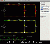
Below is a still image of his animated java applet onscreen.

It shows the square-to-sine converter circuits which come from the code in post #14.


It also shows the waveforms produced by each circuit. The bottom circuit may need to have you open a 'Show in Scope' menu, to display its waveform. It must be quirky because only the top waveform is shown when I import the circuit fresh.
 
Thank you so much everyone for your great help. Many thanks for being so much helpful! Friends, is there a very easy way to make a sinewave oscillator and amplifier, so that all the filtering hassle is removed? Can I do it myself on a veroboard? If the output is pure sinewave, I want to run about 50watts at 220volts. Can you help me with a very simple circuit design? I can't assemble complex ones. I want to feed the sinewave output of the amplifier to a 12-0-12v 5Amp step down transformer in reverse windings.
 

Dear baghu
Hi
I'm agree with syncopator . it seems good way .
There are many many ways to obtain your aim .
If you tell me a bit more explanation , that how much quality , and price do you want , i can suggest you best way to achieve your purpose .
You can use linear ways , or switch mode ways . both of them are easy , but at switch mode , systems , you'll be able to decrease the price and increase the quality .
BTW : one of simple ways , that you can do is royer oscillator ( but it's out pu is square wave ) . and it is not good way for you , i think.
if you need powers up to some KW , the switch mode ways are best choices ( as you told , you want 50 W , but if you want more powers , no problem )
And you can do it with your self
All the best
Goldsmith
 

... is there a very easy way to make a sinewave oscillator and amplifier, ..... Can I do it myself on a veroboard?
Yes, it's quite easy.
I would recommend using a Wien bridge oscillator. You can find many examples on the web, using a variety of amplitude stabilising methods. I suggest you have a search so you can decide which method you want to use.

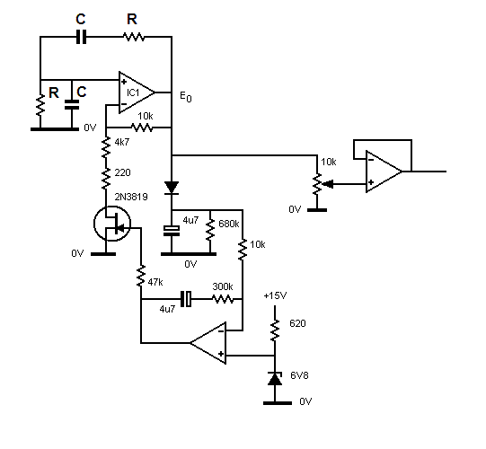
Here's one version which I designed. The amplitude control may be rather more complicated than you want, but it works well.


Wienosc2.gif


The frequency of a Wien oscillator is given by the following equation

Wienfrequency.gif


A value of 120k for the two Rs and 27nF for the two Cs give a calculated frequency of 49Hz. You may have to make small adjustments, as necessary, to get the frequency exact - if it's important.

___________________________________________________________________________________


I used the same method which you mentioned to make a 50Hz 220V power supply for my record turntable when I was living in South America, where the local mains was about 60Hz and somewhere around 110V. Neither of those figures being reliable. I did actually start with a special chip which gave a precise 50Hz out. It was derived from a crystal oscillator with a suitable dividers in the chip. The output was a square wave, which I passed through a band pass filter.
The sine wave drove a 4 -5 watt amplifer which had a reversed mains transformer at its output.
I don't think the chip is manufactured any more. But that's irrelevant
 

Status
Not open for further replies.

Part and Inventory Search

Welcome to EDABoard.com

Sponsor

Back
Top