Continue to Site

Welcome to EDAboard.com

Welcome to our site! EDAboard.com is an international Electronics Discussion Forum focused on EDA software, circuits, schematics, books, theory, papers, asic, pld, 8051, DSP, Network, RF, Analog Design, PCB, Service Manuals... and a whole lot more! To participate you need to register. Registration is free. Click here to register now.

[SOLVED] CCS PIC C and LCD Interfacing with PIC16F877A

Status
Not open for further replies.

xpress_embedo

Advanced Member level 4
Joined
Jul 5, 2011
Messages
1,154
Helped
161
Reputation
396
Reaction score
189
Trophy points
1,353
Location
India
Activity points
10,591
I am new to CCS PICC Compiler..
I want to write a simple Program using PIC C to display some data on the LCD...
But i don't know why my code doesn't works..

Here is my Code:-
Code:
//This is LCD_Example.c File

#include <Lcd_Example.h>
#define ENABLE_PIN C2
#define RS_PIN C0
#define RW_PIN C1
#define Data4 B4
#define Data5 B5
#define Data6 B6
#define Data7 B7
#include <lcd.c>

void main()
{
   set_tris_b(0x00);
   set_tris_c(0x00);
   Delay_ms(100);
   lcd_init();
   Delay_ms(100);
   lcd_gotoxy(1,1);
   lcd_putc("\fReady...\n");
   while(1);
}

/*****************************************/
//This is LCD_Example.h file
#include <16F877A.h>
#device adc=16

#FUSES NOWDT                    //No Watch Dog Timer
#FUSES HS                       //High speed Osc (> 4mhz for PCM/PCH) (>10mhz for PCD)
#FUSES NOPUT                    //No Power Up Timer
#FUSES NOBROWNOUT               //No brownout reset
#FUSES NOLVP                    //No low voltage prgming, B3(PIC16) or B5(PIC18) used for I/O
#FUSES NOCPD                    //No EE protection
#FUSES NOWRT                    //Program memory not write protected
#FUSES NODEBUG                  //No Debug mode for ICD
#FUSES NOPROTECT                //Code not protected from reading

#use delay(clock=20000000)

I am not using MPLAB IDE to write my code..
I am using PIC C IDE(PCW) to write my code..

Here is my schematic Diagram
Capture.PNG


I had searched on this matter on Google and EDABoard before posting here..

Thanks in Advance
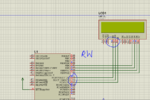
 

I am not getting any error..
But my code is not running in Proteus Simulation
 

First of all if you are just writing to LCD, and not reading anything then it is better to simply connect the R/W pin of LCD to ground.

Try this and then post the result, meanwhile i'll have a look at the code
 

First of all if you are just writing to LCD, and not reading anything then it is better to simply connect the R/W pin of LCD to ground.

Try this and then post the result, meanwhile i'll have a look at the code

No even grounding of PIN RW doesn't work..
Any other suggestions pls..
I am very new to CCS PIC C..
I had used Hi-Tech C and MikroC before and there code works fine.
But i have to learn this compiler.
 

Did you use the automatic project code generator to make that test code for the LCD? If so, it does not work; the CCS compiler uses the wrong defines! The exact same thing happened to me when I made my first LCD test program. This is what to do...

Open the LCD.C header file from the Drivers folder under installation (mine is here: C:\Program Files (x86)\PICC\Drivers). You don't need to change anything there, I'm just showing you where to find the information.

Look in the header information, it will show how to define the pin names for the LCD.

It looks like this:
Code:
////  Example of pin access:                                               ////
////     #define LCD_ENABLE_PIN  PIN_E0                                    ////
////     #define LCD_RS_PIN      PIN_E1                                    ////
////     #define LCD_RW_PIN      PIN_E2                                    ////
////     #define LCD_DATA4       PIN_D4                                    ////
////     #define LCD_DATA5       PIN_D5                                    ////
////     #define LCD_DATA6       PIN_D6                                    ////
////     #define LCD_DATA7       PIN_D7                                    ////

Note that the LCD data pins are defined as LCD_DATA4 etc. You can change the pins you use, but the defined name must be like the above. The example code that is generated by project wizard uses the wrong defined names - DATA4 is wrong - it should be LCD_DATA4 etc.

Change your defines to be like the above and try again.
 
I am using CCS PIC-C IDE to write my code...
At start-up it ask for pin configuration of LCD

and by default generates a code as follow for my connection:-
Code:
#define ENABLE_PIN C2
#define RS_PIN C0
#define RW_PIN C1
#define Data4 B4
#define Data5 B5
#define Data6 B6
#define Data7 B7

But when i read the lcd.c file
I found that this all is wrong and due to this my Proteus Simulation file is not working at all..
Means even the pins are not getting High or Low..
By looking at lcd.c file
i came up with this code..
But still it is not working
Any one pls help me
Code:
#include <Lcd_Example.h>

#define LCD_RS_PIN PIN_C0
#define LCD_RW_PIN PIN_C1
#define LCD_ENABLE_PIN PIN_C2
#define LCD_DATA4 PIN_B4
#define LCD_DATA5 PIN_B5
#define LCD_DATA6 PIN_B6
#define LCD_DATA7 PIN_B7
#include <lcd.c>

void main()
{

   set_tris_b(0x00);
   //output_b(0x00);
   set_tris_c(0x00);
   //output_c(0x00);
   lcd_init();
   Delay_ms(1000);
   while(1)
   {
      lcd_gotoxy(1,1);
      while(1);
      Delay_ms(1000);
      lcd_putc("\fReady...\n");
      Delay_ms(1000);
   }
}


---------- Post added at 23:04 ---------- Previous post was at 23:01 ----------

Did you use the automatic project code generator to make that test code for the LCD? If so, it does not work; the CCS compiler uses the wrong defines! The exact same thing happened to me when I made my first LCD test program. This is what to do...

Open the LCD.C header file from the Drivers folder under installation (mine is here: C:\Program Files (x86)\PICC\Drivers). You don't need to change anything there, I'm just showing you where to find the information.

Look in the header information, it will show how to define the pin names for the LCD.

It looks like this:
Code:

//// Example of pin access: ////
//// #define LCD_ENABLE_PIN PIN_E0 ////
//// #define LCD_RS_PIN PIN_E1 ////
//// #define LCD_RW_PIN PIN_E2 ////
//// #define LCD_DATA4 PIN_D4 ////
//// #define LCD_DATA5 PIN_D5 ////
//// #define LCD_DATA6 PIN_D6 ////
//// #define LCD_DATA7 PIN_D7 ////

Note that the LCD data pins are defined as LCD_DATA4 etc. You can change the pins you use, but the defined name must be like the above. The example code that is generated by project wizard uses the wrong defined names - DATA4 is wrong - it should be LCD_DATA4 etc.

Change your defines to be like the above and try again.

Thanks for your help..
And i found it few minutes ago..
But the Program still not working..
I had posted my code in above post can you tell me what is the Problem now...

Is CCS not a good compiler.. Its a big mistake in compiler..
I am suffering due to this from last 3 Days..
 

First of all if you are just writing to LCD, and not reading anything then it is better to simply connect the R/W pin of LCD to ground.

Testing the busy flag, rather than using set delays, is always the preferred method of implementing a LCD interface, that being said the compiler libraries must support this feature if they are utilized which is another question.

Also not all LCDs, even those claiming to be HD44780 compatible, fully implement the busy flag feature.

@arunsharma0731

Although, I'm not a big fan of CCS Compilers, I'll see what I can find to assist you.

BigDog
 
My Code is as Follow:-
Code:
#include <Lcd_Example.h>

#define LCD_RS_PIN PIN_C0
#define LCD_RW_PIN PIN_C1
#define LCD_ENABLE_PIN PIN_C2
#define LCD_DATA4 PIN_B4
#define LCD_DATA5 PIN_B5
#define LCD_DATA6 PIN_B6
#define LCD_DATA7 PIN_B7
#include <lcd.c>

void main()
{

   set_tris_b(0x00);
   //output_b(0x00);
   set_tris_c(0x00);
   //output_c(0x00);
   lcd_init();
   Delay_ms(1000);
   while(1)
   {
      lcd_gotoxy(1,1);
      Delay_ms(1000);
      lcd_putc("Arun Sharma");
      Delay_ms(10000);
   }
}


But when i run the Proteus Simulation
I am getting a Strange Thing

Capture.PNG

See the RW pin it is always High..
I don't know why..
It must be low.
When writing data to LCD
I am much more confused now.
 

Two quick thoughts (I'm about to eat)...

Take out the set_tris lines, the compiler will do that for you in the background.

Do you have a main.h that should be included? CCS usually makes one.

Your code looks OK apart from that - check your connections, LCD contrast connection, etc.
 

Just glancing at your design, I have some questions.

All the I/O pins in PORTC are multiplexed with several peripheral modules. While they are a valid option a more efficient use of pins would be to utilize the remain pins on PORTB.

Or are the remaining pins in PORTB planned for a future purpose? What about PORTD these pins have no interrupts or peripheral modules associated with them and are strictly Digital I/O?

BigDog

---------- Post added at 19:02 ---------- Previous post was at 18:57 ----------

Your code looks OK apart from that - check your connections, LCD contrast connection, etc.

FoxyRick brings up a valid point, Proteus may expect you to make the Vdd,Vss and Vee connections.

BigDog
 
Tried Everything..
FoxyRick brings up a valid point, Proteus may expect you to make the Vdd,Vss and Vee connections.

BigDog
Placed VDD,VSS,VEE
No Result
Two quick thoughts (I'm about to eat)...

Take out the set_tris lines, the compiler will do that for you in the background.

Do you have a main.h that should be included? CCS usually makes one.

Your code looks OK apart from that - check your connections, LCD contrast connection, etc.

Removing TRIS lines..
No Result...
I am getting some warning in Proteus simulation window

Capture.PNG

I had also changed control lines to PORTD but still doesn't work
 

When i open the CCS PIC C IDE..
It asked me to save the project i saved it by the name Lcd_Example.h
This is that..
It contains
this
Code:
//Lcd_Example.h
#include <16F877A.h>
#device adc=16

#FUSES NOWDT                    //No Watch Dog Timer
#FUSES HS                       //High speed Osc (> 4mhz for PCM/PCH) (>10mhz for PCD)
#FUSES NOPUT                    //No Power Up Timer
#FUSES NOBROWNOUT               //No brownout reset
#FUSES NOLVP                    //No low voltage prgming, B3(PIC16) or B5(PIC18) used for I/O
#FUSES NOCPD                    //No EE protection
#FUSES NOWRT                    //Program memory not write protected
#FUSES NODEBUG                  //No Debug mode for ICD
#FUSES NOPROTECT                //Code not protected from reading

#use delay(clock=20000000)

//and Lcd_Example.c is posted above
 

I found the following example code, which implements an LCD and Keypad interface using a PIC16F84:

LCD & KEYPAD INTERFACE CIRCUIT

The above example utilizes its own routines rather than use the CCS's routines contained in lcd.c.

And I'm interested in what is contained in Lcd_Example.h as well.

BigDog

---------- Post added at 19:36 ---------- Previous post was at 19:29 ----------

Here is another example which uses CCS's routines in lcd.c:

Basic LCD Control using CCS

Note the example states:

be sure to modify the flags in the LCD.C file for your particular LCD!

You want to ensure you set the #defines within the file that they are used.

As per Standard C, the scope of #defines is only until the end of file of which they are contained.

Therefore setting the #defines use by lcd.c from within the main.c has no effect.

BigDog
 
you have wrongly set RW,EN and RS in your code according to your proteus file.

Actually in this case, due to CCS poor coding practice of inclusion of C files, it actually makes no difference.

The following statement:

Code:
#include <lcd.c>

In effect is substituted for the contents of the lcd.c file.

Therefore we are BOTH wrong.

BigDog
 
you have wrongly set RW,EN and RS in your code according to your proteus file.

Actually i had manipulated the content of file so many times...
thats why...

Code:
/*#include <Lcd_Example.h>

#define LCD_RS_PIN PIN_C0
#define LCD_RW_PIN PIN_C1
#define LCD_ENABLE_PIN PIN_C2
#define LCD_DATA4 PIN_B4
#define LCD_DATA5 PIN_B5
#define LCD_DATA6 PIN_B6
#define LCD_DATA7 PIN_B7
#include <lcd.c>

void main()
{

   Delay_ms(100);
   lcd_init();
   Delay_ms(1000);
   while(1)
   {
      lcd_gotoxy(1,1);
      Delay_ms(1000);
      lcd_putc("Arun Sharma");
      Delay_ms(10000);
   }
}*/
#include <lcd.c>

void main()
{
   lcd_init();
   lcd_gotoxy(1,1);
   lcd_putc("Welcome to EGYPT");
}

I had connected my LCD controls to C0,C1 and C2
 

Okay Sure...
And Thanks

---------- Post added at 00:21 ---------- Previous post was at 00:19 ----------

Thank You everyone...
But my problem is not solved yet...

:-(
 

Is the use of the CCS Compiler a necessity or are you just attempt to learn a new compiler?

BigDog
 

Status
Not open for further replies.

Similar threads

Part and Inventory Search

Welcome to EDABoard.com

Sponsor

Back
Top