Continue to Site

Welcome to EDAboard.com

Welcome to our site! EDAboard.com is an international Electronics Discussion Forum focused on EDA software, circuits, schematics, books, theory, papers, asic, pld, 8051, DSP, Network, RF, Analog Design, PCB, Service Manuals... and a whole lot more! To participate you need to register. Registration is free. Click here to register now.

[SOLVED] UPS Transformer windings

Status
Not open for further replies.

nazeerhussain

Newbie level 5
Joined
Nov 24, 2011
Messages
9
Helped
0
Reputation
0
Reaction score
0
Trophy points
1,281
Activity points
1,356
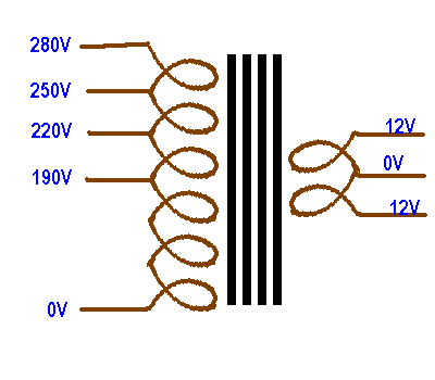
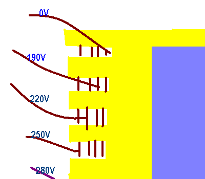
Basically I want to build ups with 12-0-12/220V topology, that is roughly 1000va capacity. The thing I am stuck on right now is that for this power range, the windings of most ups transformers available in local market are not properly marked. Physically there are five winding taps on output side, in which only three are to be used (INV, CHG & Neutral) for connections between ups board and transformer. I cannot understand how I am supposed to work out.

Does any body have any information about the transformer windings? How to check and connect it? What output voltages you think will be useful.

Thanks for the help
Regards,
nazeerhussain
 

These five taps are on primary side on single winding.

35_1323968058.png

These can be easily identified this way,
65_1323968684.png


0V is common, Connect 220V to charging. Connect 250V to inverter out.
Deeper most is 0V.It is start of winding so is single wire. Outer most is 280V. It is end of wire hense it is single wire. Others are double because they are looped back. These can also be identified by checking resistance with a digital meter. Resitance between 0V and 190V is 2.7 ohm and it is 4 ohm between 0V and 280V.(Value for voltages and resistance are just for example. Actual may be different). Sometimes there will be 4 or 6 wires. Voltage and charging can be increased and decreased by shifting connection to nearby loop.
 
Thank you very much 'ALERTLINKS' for your quick technical reply.This is the complete diagrams,really i improved my bank of knowledge.Provided information would make such a project easier to construct/ adjust/ maintain.Thank you again for kind response.
Regards,
 

Thank u both 'nazeer & alterlinks' to give us some information about ups....

- - - Updated - - -

I ve built a home made ups myself. And successfully its works good with having only one problem in it.
The problem is "when i put some heavy load above from 100 watts its voltage varies (low) from 280 v to 130v.
I didn't understand this problem.
Can any body help me about this problem PLZzzzzzz

(i ve use D 1047 transistor , 15 amp transformer , 1 ups osculation circuit , two diodes & 1 220 volts relay.
 

Status
Not open for further replies.

Similar threads

Part and Inventory Search

Welcome to EDABoard.com

Sponsor

Back
Top