joeka
Newbie level 4
Hi,
I'm currently developping a system to output PAL video from a camera.
I worked on a former project where the ouput video was in VGA. The video structure was like this : FPGA => DAC => VGA.
In order to add PAL format to this project, I add an AD725 to convert VGA to PAL. I proceed as shown page 12 on the datasheet : http://www.analog.com/static/imported-files/data_sheets/AD725.pdf
I code the new timings signals (hsync and vsync) according to PAL standard as shown on http://martin.hinner.info/vga/pal.html
I used two state machines to do it with a 13.5Mhz clock
constant v_long_sync : integer := 371; -- 27.5us
constant v_short_sync : integer := 32 ; -- 2.4us
constant v_long_delay : integer := 400; -- 29.6us
constant v_short_delay : integer := 61; -- 4.5us
constant h_front_porch : integer := 0;
constant h_sync : integer := 54; -- 4 us
constant h_back_porch : integer := 108; -- 8us
constant h_left_border : integer := 0;
constant h_video : integer := 702; -- 52us
constant h_right_border : integer := 0;
I tried my code on ModelSim successfully.
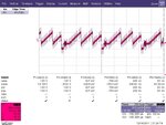
However, when i displayed a pattern on a TV, the image quality is not what i expected (some kind of diagonal lines moving but quite perceptible) . I try to test the signal directly at the output of the AD725 and I get this signal for the composite output :

I think that the noise is responsible for the quality of the picture and i'd like to solve this noise problem. Any idea ?
Furthermore, I measured the frequence of the pal quartz I used and this one is quite different from the PAL clock needed (17.734475MHz) (about 600-1000Hz difference). Do this clock need to be exact ?
I really want to improve the quality of the picture.
Kind Regards.
Joeka
I'm currently developping a system to output PAL video from a camera.
I worked on a former project where the ouput video was in VGA. The video structure was like this : FPGA => DAC => VGA.
In order to add PAL format to this project, I add an AD725 to convert VGA to PAL. I proceed as shown page 12 on the datasheet : http://www.analog.com/static/imported-files/data_sheets/AD725.pdf
I code the new timings signals (hsync and vsync) according to PAL standard as shown on http://martin.hinner.info/vga/pal.html
I used two state machines to do it with a 13.5Mhz clock
constant v_long_sync : integer := 371; -- 27.5us
constant v_short_sync : integer := 32 ; -- 2.4us
constant v_long_delay : integer := 400; -- 29.6us
constant v_short_delay : integer := 61; -- 4.5us
constant h_front_porch : integer := 0;
constant h_sync : integer := 54; -- 4 us
constant h_back_porch : integer := 108; -- 8us
constant h_left_border : integer := 0;
constant h_video : integer := 702; -- 52us
constant h_right_border : integer := 0;
I tried my code on ModelSim successfully.
However, when i displayed a pattern on a TV, the image quality is not what i expected (some kind of diagonal lines moving but quite perceptible) . I try to test the signal directly at the output of the AD725 and I get this signal for the composite output :

I think that the noise is responsible for the quality of the picture and i'd like to solve this noise problem. Any idea ?
Furthermore, I measured the frequence of the pal quartz I used and this one is quite different from the PAL clock needed (17.734475MHz) (about 600-1000Hz difference). Do this clock need to be exact ?
I really want to improve the quality of the picture.
Kind Regards.
Joeka
