Continue to Site

Welcome to EDAboard.com

Welcome to our site! EDAboard.com is an international Electronics Discussion Forum focused on EDA software, circuits, schematics, books, theory, papers, asic, pld, 8051, DSP, Network, RF, Analog Design, PCB, Service Manuals... and a whole lot more! To participate you need to register. Registration is free. Click here to register now.

Improving battery life when running LED's

Status
Not open for further replies.

Aussie_Burger_The_Works

Newbie level 4
Joined
Dec 8, 2011
Messages
6
Helped
0
Reputation
0
Reaction score
0
Trophy points
1,281
Activity points
1,334
Hello, I have been trying to improve my battery life on a project that flashes 12V led strip. My idea was to turn the strip on and off rapidly >50hz so the flashing would not be noticeable but I could effectively halve my current consumption leading to greater battery life.

My circuit is run off a PIC micro (12F683) switching a MOSFET (P16NF06) however once I have wired the circuit up I get the following waveforms on the CRO. At the moment I am driving the MOSFET with a square wave out of my signal generator (~10v p-p).


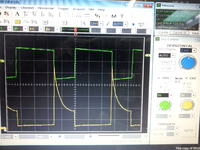
The green waveform is at the gate to the MOSFET and the Yellow is at the Drain.

Thanks in advance
 

You're doing the test at about 120Hz which is fine. But the duty cycle is about 64% which means that the LEDs are on longer than they are off. The obvious solution to reducing power consumption is to reduce the duty cycle - less on time, more off time.

The drain waveform shows turn-off spikes. This implies that there is an inductive component in the load. Please elaborate on what you mean by "12V LED strip". Are they simply LEDs with series resistors or with a more sophisticated LED driver?

Also, please reduce the size of your image before uploading. It's unnecessarily large, wasting bandwidth and prolonging download time, especially for those with slow connections. An image one quarter of your current size in both directions - about 800x600 - is more than enough for that kind of image and will reduce file size to one-sixteenth at the same quality.
 

What's the objective, flashing or continuous light? You should choose the operation mode according to this requirement.

In a first order, total LED intensity, as percepted by the human eye, will be proportional to the average current, or in other words the true battery load as long as no switch mode voltage conversion is involved. In other words, flashing a LED can't increase battery life. In an exact analysis, the LED efficiency slightly drops at higher currents.

Additional requirements apply for white LEDs that have to be operated in a certain current range to achieve the specified color temperature. Or, if flashing is the objective.

My computer has a print key to capture screens, by the way. You can copy screenshots to a *.jpg or *.gif file.
 

Hey, yes unfortunately my square wave signal generator is built around a 555 timer and tends to vary the duty cycle as the frequency changes, but this being a problem I will resolve another time, my idea is to ideally have a 50% duty cycle or less.

The LED strip is simply a flat flexible strip with 3M double sided tape on the back it consists of series circuits in parallel with each other with each series circuit consisting of 3 leds with both a 39R and 51R resistor in the series circuit. The strip is designed to be cut in 3 led segments approximately 5cm. There is no LED driver.

I have found the problem to be greater with higher current loads, 5m strips as opposed to 2m and at higher operating frequencies. These to me indicate in inductive component but the circuit is purely a signal generator switching a MOSFET.

The circuit will be battery powered although at the moment it is powered of a commercial SMPS could this possible be the cause as they generally have inductive filters?

Okay no problem I will do that in the future.

---------- Post added at 18:56 ---------- Previous post was at 18:48 ----------

At the moment I am running the constantly on and achieving approximately 8 hours from a 18AH SLA battery, I would like to get more out of the battery as I cant increase the capacity or change the battery type. My Idea was to flash them at a rate >50hz with a duty cycle of 50% or less so they appear constantly on and hopefully I can half the current consumption?
 

I should have asked this before: What colour are the LEDs? If they're red or amber, then you can string 4 in series with a 12V supply, reducing the number of strings in parallel from 4 to 3 and thus saving power.

And how bright do you need them to be? That will dictate whether it's feasible to reduce the current through each series string. Is the current setup about bright enough or unnecessarily brighter than they need to be?

Regarding the inductive filter in the SMPS, they shouldn't cause the spikes because the inductive component is isolated from the load by capacitors. Additional caps near the load will also help.
 

The LED's are pure white but as they are a ready made it wont be possible change there configuration. In the future I will request the resistors be removed from each series string and then I will run the strip off a constant current source buck converter to improve the efficiency.

Efficiency is not my concern at the moment. I am purely after a longer battery life with this method the only way I can think off at the moment. I have visually compared a strip being switched at 100hz and one constantly on and couldnt see much of a difference if any which leads me to believe that this may be a viable solution? The strips can be dimmed down a bit without a problem as they are slightly brighter than necessary.

The inductive spike is the worrying factor as it is peaking at 30v off a 12v supply which cannot be good for any of the circuitry or the LED's themselves. Although the source of this is a mystery.
 

Status
Not open for further replies.

Part and Inventory Search

Welcome to EDABoard.com

Sponsor

Back
Top