Vermes
Advanced Member level 4
Assumptions:
- two-phase bipolar motor
- maximum phase current: 12A
- operating voltage of about: 120V
- microstep min. 16
- opto-isolated inputs
- resistant to short circuits, etc.
- quick and easy assembly in the housing
Construction
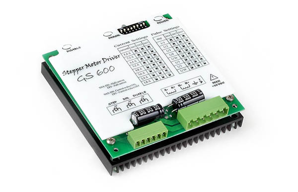
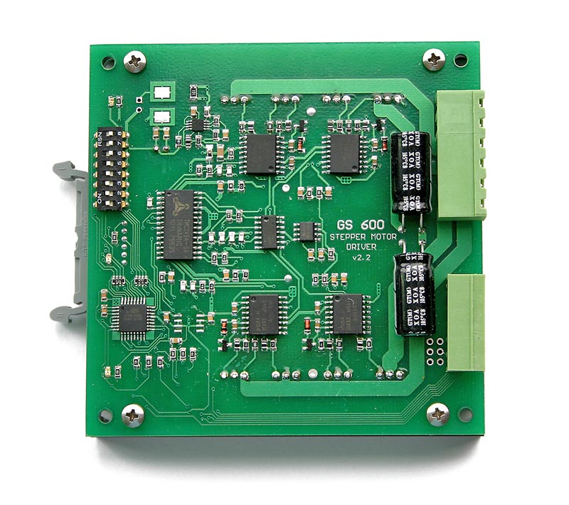
TMC249 was the control system. It has only SPI interface, so a processor converting classic signals STEP/DIR to frames sent by SPI was necessary. The processor was Atmega88 clocked by an internal oscillator 8MHz. Terminal steps transistors – IRF640 – are driven by drivers IR2110. This may not be the latest design, however, they are relative cheap and available. The frequency of obstructive is around 36kHz – it heats up a little more then at 20-25kHz, but the work is much more pleasant, and the motor does not squeak when stopped. A small inverter ensures powering the logic. Thanks to that, it was possible to obtain a wide range of power voltages values 16-98V while maintaining a relatively high efficiency of about 85%.
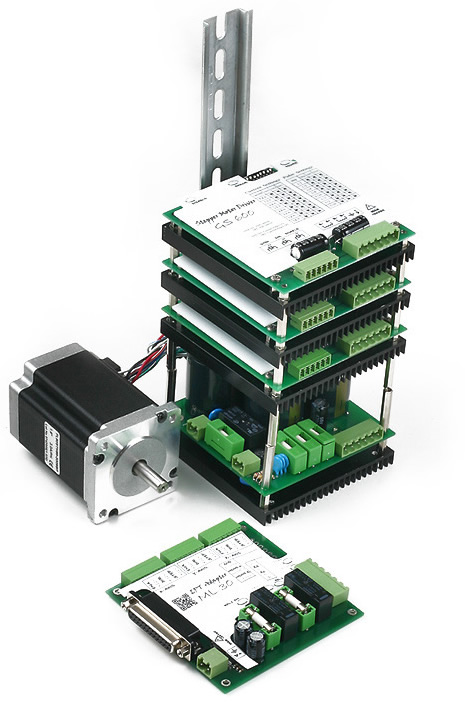
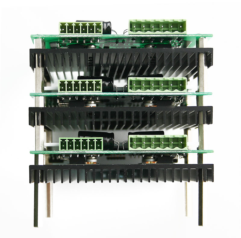
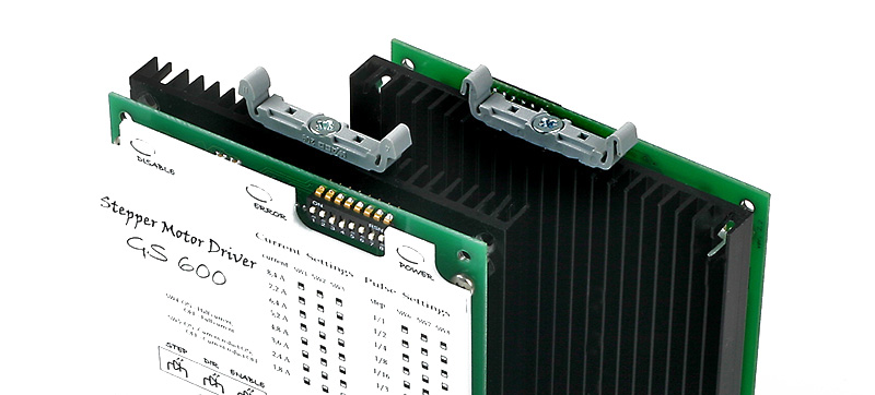
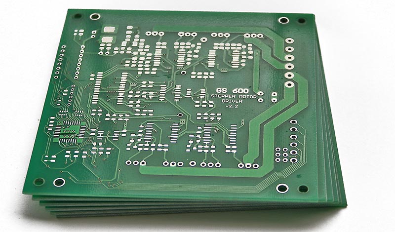
If for mechanical part. The driver is mounted to a heat sink with dimensions of 100x100mm. Also bridges transistors on the bottom of the board are mounted to the heat sink. The driver was made in two versions: with passive and active cooling. At the highest settings of the phase current, even a slight movement of air is required – so there was no need to remember that after assembling, each driver was equipped in a small ventilator with dimensions of 30x30mm. But it is sufficient to limit the current to about 4-5A, so the driver was able to work only cooled by the heat sink. All the elements can be screwed one to another and mounted to DIN bar, using the handle visible in the pictures. Module in the form of three drivers, power supply and adapter LPT after assembling is stiff and well-kept on the bar.
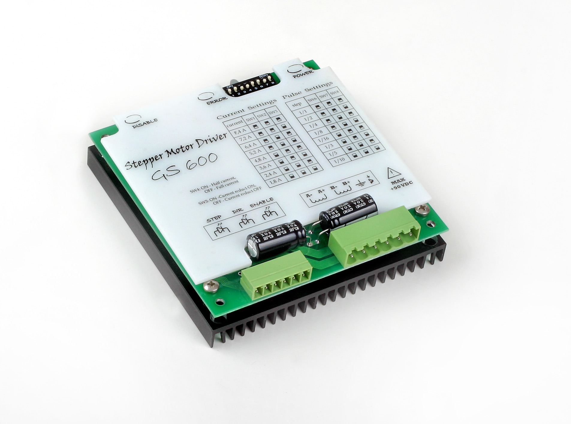
- motor type: two-phase bipolar
- voltage: 16V-98VDC
- division of steps: 1, 1/2, 1/4, 1/8, 1/16, 1/3, 1/5, 1/10
- motor phase current: 8,2A, 7,8A, 7,2A, 6,8A, 6,2A ,5,8A, 5,2A, 4,2A, 4,1A, 3,9A, 3,6A, 3,4A, 3,1A, 2,9A, 2,1A
- maximum signal STEP and DIR frequency – 100kHZ – allows to achieve the speed of 720 rpm
- overvoltage and short circuit protection
- reverse polarity voltage protection
- opto-isolated control inputs STEP/DIR/ENABLE with a digital filter
- coil current reduction at standstill (above 500ms) – option selected by a DIP switch
Link to original thread (attachment) – Sterownik silnika krokowego