Vermes
Advanced Member level 4

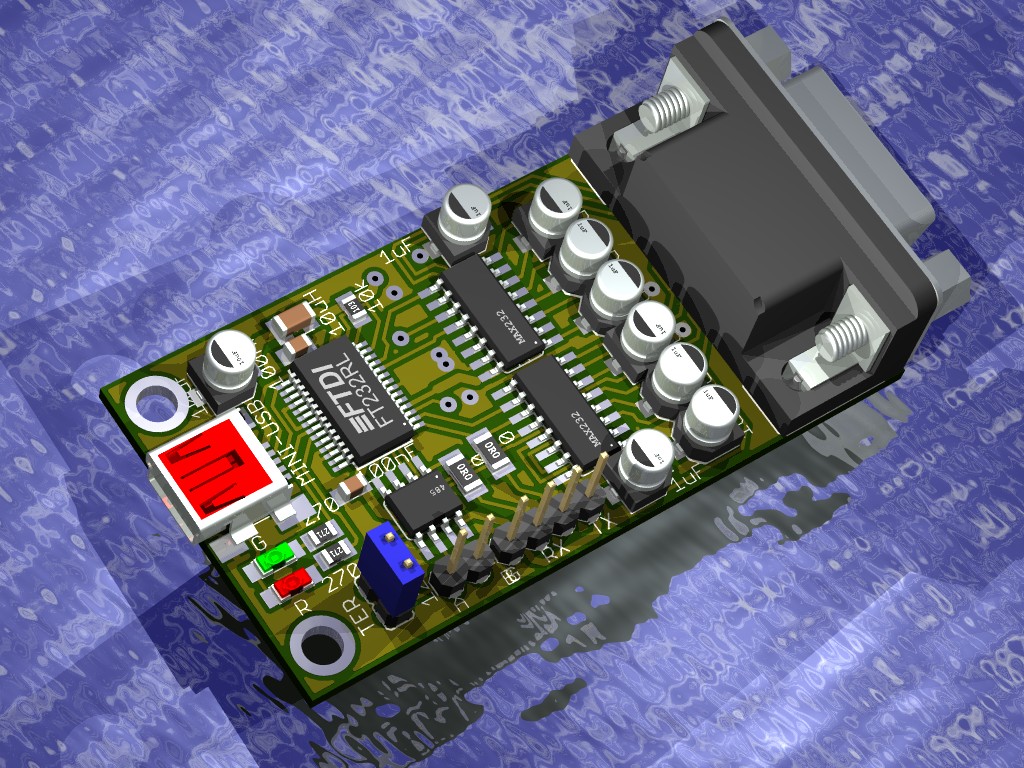
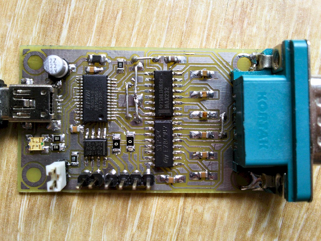
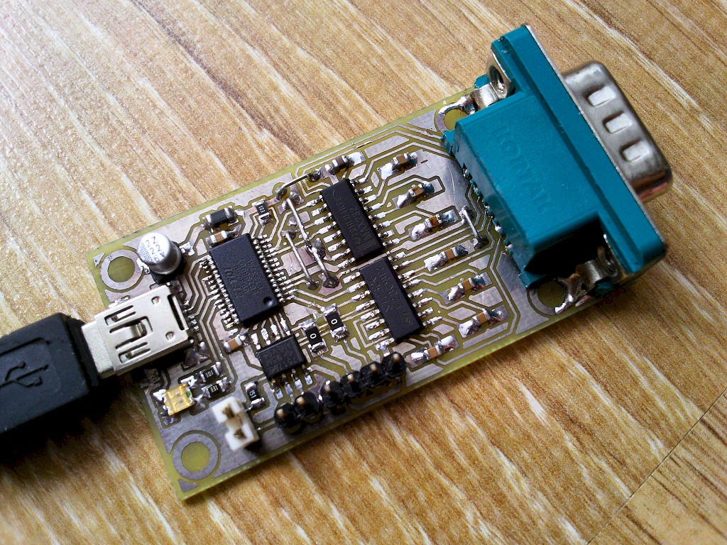
Presented device is 3in1 converter: USB – RS232, RS485 and UART. A fully dedicated system FT232RL acts as the converter. It is seen in the system as a COM port, and is assisted by two MAX232 and MAX485 systems. Any settings of the converter can be made through the system as it is in a normal COM port, supported speeds 110-921600bps.
One-sided board with dimensions of 30mm x 58mm, all surface mount components, despite the COM terminal (DB-9M, male DB9). There are two indicator diodes on the board: red TX and green RX, attached to the pins CBUS0 and CBUS1 of FT232R system. Current limiting resistors are typically 270ohm, but they should be chosen to the LEDs power, red one usually requires less voltage.
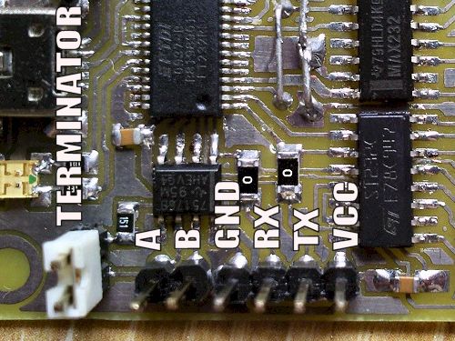
There are three connectors available:
RS232 – The role of voltages translator TTL – V.24 have two MAX232. Systems have the load pump generating voltage +9V and -9V, necessary to ensure compliance with V.24. Systems RS232 reverse logic, high state at the input will give a low state at the output and vice versa.
RS485 – The board has also a RS485 converter system (SN75176), its transmitter is controlled by a TXDEN line from pin CBUS2 of FT232R system, so that it is active only when sending character and is done automatically. Its receiver in this converter is configurable by assigning specific functions to pin CBUS3 of FT232 system. It can be done using the program MPROG. “TXDEN” function – the receiver will be turned on all the time, but will be turned off automatically during the transmitting – echo will not be received. “PWRON” - the receiver will be permanently attached, echo will be received. “I/O” - the receiver off, the output in high impedance state, does not block the READ line, allowing to use the other connectors of the converter. NOTE – default, the receiver is working! Differential output A and B in the form of HEADERS, on the PCB there is also a jumper enabling the resistor of the terminator 120ohm.
UART TTL – Lines TxD and RxD in TTL standard, derived in the form of HEADERS for direct connecting the systems that use asynchronous transmission to voltage levels 0V-5V, such as microcontrollers. RxD pin is shared with the circuit RS232 output, which has no possibility of switching it into high impedance state while the system is not used (0V at RS input). In return for such a condition of the input, it serves high state on RxD pin, preventing it from directly sharing with another transmitting device. The easiest way to work around this conflict was to combine the output of the system to read line through the 10K resistor – FT232 system receives the data correctly, and using a different transmitter to UART TTL connector, the current needed to download RxD pin will not be greater than 1mA.
The system is powered from USB port, while introducing to the computer, it informs that its demand for current is 90mA. It is good to increase this value due to the conversion system RS485, which demand for current is much greater. Program MPROG will be needed for this. Through this program the content of internal memory EEPROM can be changed and adapted to the needs. First, install the drivers. Download VCP_DRIVER (virtual com port), after connecting the device, indicate the package with the driver to the installer.
Assembly
- COM socket was soldered from the top – a socket with undeveloped terminals is needed in order to be easy to solder. For the built socket as in this case, if the 5 pins from the edge can be reached with a thin tip, 4 pins from the center should be connected slightly differently.
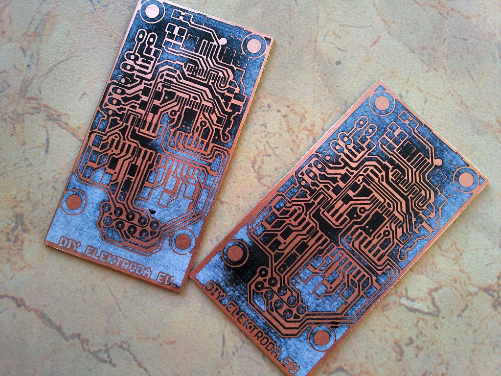
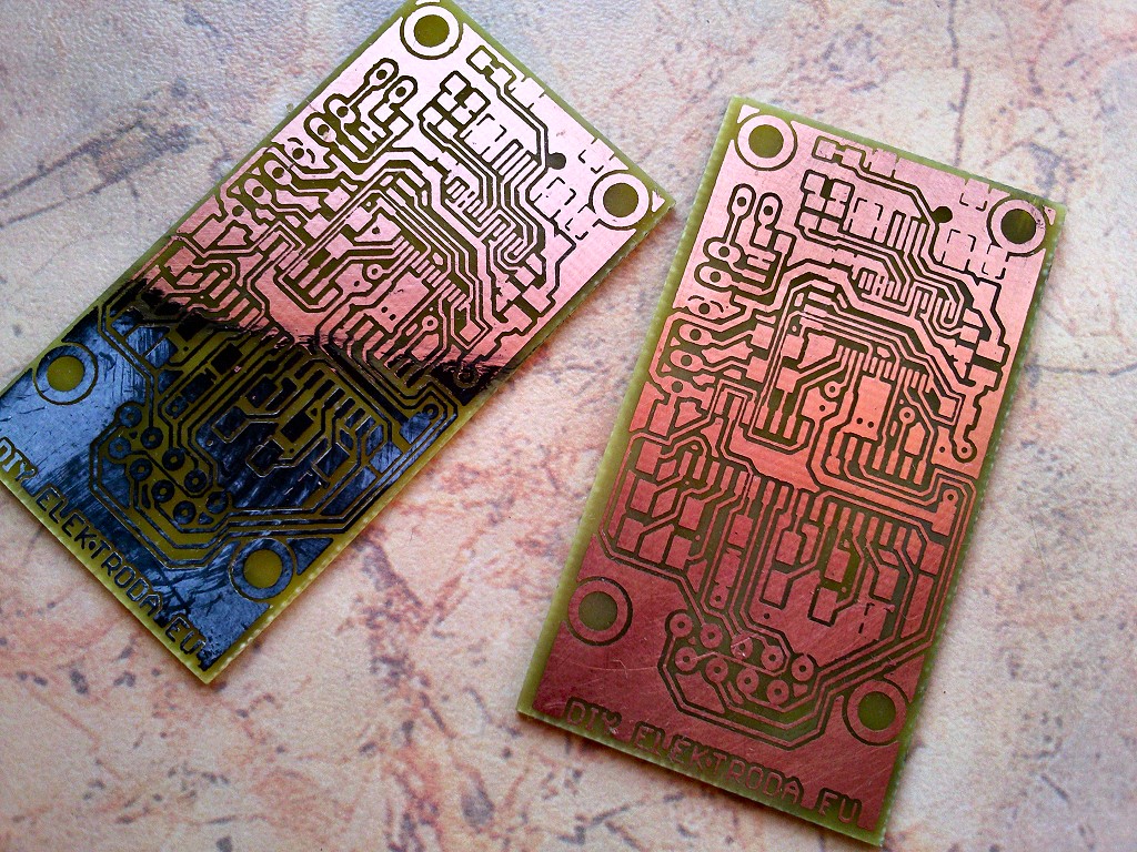
- The paths pass between the systems SOIC pads. Their thickness at these places is 10mils, and the gaps even less – so the PCB should be carefully made to avoid short-circuits.
- Spaces for MAX232 systems' capacitors were designed for soldering the SMD electrolytes in 0405 housings. Ceramics or other capacitors may also be used, with appropriate values.
- 5 connections by jumpers should be made on the PCB.
Notes
To check the system RS232, short pins 2 and 3 on the DB9 plug – echo of what we sent should be received in the terminal, and both diodes should blink once. If this does not happen, pins TX and RX should be shorted in the TTL connector – if the PCB does not contain assembly errors, this has to work properly. In case of problems with the converters MAX232, voltages on legs 2 and 6 should be measured. They should be about +9V and -9V. If not, check whether the correct capacitors were used for integrated voltage converter – version MAX232 requires 4x 1uF, while the MAX232A requires 4x 100nF. To check the system RS485, just turn its receiver. The PCB in photos is a prototype, the lack of the 1K resistor separating RxD line from MAX232 output – upgraded project is in the annex.

Link to original thread (attachment) – Konwerter 3w1 - USB do RS232, RS485, UART