ALERTLINKS
Advanced Member level 4
If you are feeding 100 watts, you cant take out 110 watts. Voltage and current vary, but their product remains the same.I consider about driving transducer. I want to drive 60W transducer. And for this operation, I want to use 70W-80W transformator. But how can I be sure that my transducer will not take upper 60W power. Some frequency such as resonance frequency, transducer may take maximum power,right? So maybe my transformer will also be damaged. Second question : is it possible that high voltages on the transducer side effects my H-bridge power circit? if it is possibble, how can I recover my power circuit?
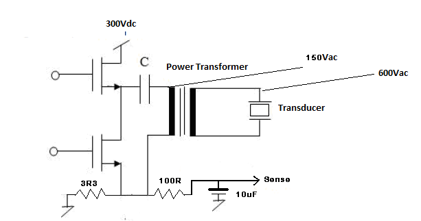
In your hbridge voltage is 300V. If you feed 90 watts input to bridge, it will be drawing 90/300=0.3A =300mA.
If you put a resistor of 3.3 ohm in series to source of lower FET so that all current pass through it. 0.3 A passing through 3.3 ohm resistor will produce 0.3 x 3.3 = 0.99 volts. By monitoring this voltage, maximum power allowed can be controlled.
PIC can sample this voltage through ADC module and stop or reduce PWM. If your transducer is china made, dont drive it at maximum capacity. It also need good contact with other surface to pass vibrations generated. Put a good quality 100mA fuse in sries with transducer.(600v x 0.1A =60 Watts). Further you can monitor DC bus voltage and output current/voltage. There are loss of power in terms of heat etc, you may get 10% less power in output.