Continue to Site

Welcome to EDAboard.com

Welcome to our site! EDAboard.com is an international Electronics Discussion Forum focused on EDA software, circuits, schematics, books, theory, papers, asic, pld, 8051, DSP, Network, RF, Analog Design, PCB, Service Manuals... and a whole lot more! To participate you need to register. Registration is free. Click here to register now.

What are these components? (Old 70's Turn-Table, 8 Track Receiver)

Status
Not open for further replies.

scottam

Newbie level 4
Joined
Oct 29, 2011
Messages
6
Helped
0
Reputation
0
Reaction score
0
Trophy points
1,281
Activity points
1,341
So I found this pretty nice Pioneer H-2001 receiver which works great mechanically, but the right channel on the amplifier circuit board is blown. Someone probably had too wild a party listening to a pink floyd vinyl back in the day.

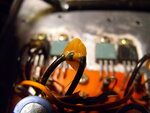
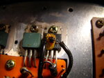
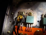
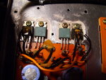
In any case, I see a couple resistors are burned which I can easily replace, but there are also some odd looking components glued to the tops of the power transistors (I think that's what they are... one is labeled C1173 [black one] and the other A473 [green]). On the right channel of the circuit, these components are fried, but on the left they are fine. They look a bit like some sort of ceramic capacitors, but there are no markings beyond half of it being painted black.

I've attached photos below. Can anyone tell me what these might be?

Thanks!
Scott
 

Attachments

  • DSCF0675.JPG
    DSCF0675.JPG
    390.5 KB · Views: 80
  • DSCF0678.JPG
    DSCF0678.JPG
    425.3 KB · Views: 98
  • DSCF0680.JPG
    DSCF0680.JPG
    440.1 KB · Views: 68
  • DSCF0682.JPG
    DSCF0682.JPG
    418 KB · Views: 78

These are either diodes or NTCs used for thermal stabilization of the power stage bias current. A multimeter can tell.
 
Ah, NTC makes sense seeing as they are glued onto one of the few components that tend to get warm. I'm a bit rusty on my electronics; if I run a multimeter across a non-fried on and it shows a resistance, it's an NTC, and if not a diode?

Also, seeing as this thing is so old, will I have to run resistance-temperature curves on the functional ones to find a replacement part with similar properties, or would I just be able to slap a resistor with the same resistance as a functional NTC at ambient temperatures?

Also, not sure if this is your area of expertise, but what sort of glue should I use to stick these guys back on?
 

The resistor in the picture seems to be burned and the insulator that was close to the resistor seems to be melted

Snap1.gif

Alex
 
Thanks Alex!

Yeah I saw that upon opening (the residual smell kinda hinted at it, having burned a lot of resistors as a kid). The one next to it looks like it over heated as well. I'll have to replace them as well. Fortunately it looks like the transistors fared well.

Upon further inspection, the other burned component (which may be an NTC or thermistor of some sort) is *white* and black, not beige as the picture leads one to believe. The glue obscured the true color.
 

Hi Scott,
I did try to locate my old books for circuit diagram of this amplifier but sorry. The C1173 is an NPN transistor (2SC1173) and A473 is a PNP transistor (2SA473). These both transistors were used in the output stage as complimentary pair. If my memory is still with me, these are Diodes (MA23 or MA26), you can check it, just remove one side leg and check with DMM for resistance or a diode. If NTC the resistance should be between 10Ω~25Ω.
 
Thanks for the help Raza! I, too, had trouble locating a similar circuit diagram for this particular amplifier. I do have one question: if they are diodes, why would they be glued to the top of the amplifying transistors? I don't have a multimeter quite yet, but I ordered one that should arrive soon. I moved recently and so had to leave all my equipment and components back home.

Thanks!
Scott
 

if they are diodes, why would they be glued to the top of the amplifying transistors?
For the same purpose as you would use thermistors: To stabilize the bias current of the output transistors, as previously said. Actually, the black and white marking of the parts clearly suggests a diode polarity sign.
 
Interesting, it's a diode package I had never encountered before, though as you note, the black/white markings are indicative of polarity. I tried locating information on MA23 and MA26 diodes on google, but wasn't able to find any part equivalents. I apologize for the ignorance on my part, but what would be my best-bet as far as replacing them with parts I can find today?

Thanks!

---------- Post added at 15:29 ---------- Previous post was at 15:23 ----------

I did find this: **broken link removed**, which has a similar looking package and application as detailed above, and then found this: MA26 Semiconductor (Transistor, diode, IC) Cross reference, which details replacements. Does this look correct?
 

The interesting point is, that MA26 is explicitely specified as compensating element with a rather tight voltage range. That looks very plausible. If I calculated right, a standard 1N400x isn't far from the MA26 specification.
 
Interesting -- I suppose I can pop in a 1N400x and see if it works/sounds okay. It's already fried, so it's not really like I can do too much additional damage. Thanks!

---------- Post added at 16:36 ---------- Previous post was at 15:48 ----------

So I also found that the 1s1210 diode is basically the same and used in similar audio circuits, but it's "brother" 1s1212/vd1212 is often replaced with 1N4448 or a 1N4148 series pair. What do you think?

Looking at the datasheets, they seem to have much different Vf tolerances from the MA26, but will this matter as far as the temperature coefficient (which I assume relates to the bias correction)? I'm not exactly a diode expert.

Thanks!
 

Scott,
These diode are integrated in the circuit just to stabilize the transistor's bias voltage. And these are stuck to the transistor bodies to pick heat of the output stage transistors quickly and control bias voltage in Negative Temperature Coefficient fashion. Here is the datasheet, though I can not read some of its columns.
View attachment MA26.pdf

So I also found that the 1s1210 diode is basically the same and used in similar audio circuits, but it's "brother" 1s1212/vd1212 is often replaced with 1N4448 or a 1N4148 series pair. What do you think?
Yes you are right 1S1212 ir 1N4148 are also used in its place. Even some designs do integrate NTC in the place. I have lost a lot of my books while moving country to country (part of my job) I tried to locate the exact diagram for the amplifier but :-(.
I have some diagrams of the old old amplifiers (around 1973~1975) if you want I can send you scanned images. Still I am trying to find the diagram, if I do will post it here.
 
As a rough approximation, you can assume that silicon diodes (and transistor BE junctions) have a temperature coefficient of -1.9 mV/degree C. The diodes are simply expected to show the same temperature coefficient as the transistors, so if you feed a constant current to the diodes, you'll get a constant collector bias current of the output stage. For a complementary BJT output stage, you'll need two compensation diodes, for complementary darlington four of it.

Diodes of different rated current (and respectively different junction area) have different forward voltages at a specific current. The output stage is designed for specific diodes, using an unsuitable type would result in a too low or too high bias current. There may a means to adjust the bias current, e.g. a potentiometer. Otherwise you have to rely on available diodes. When trying with a large area diode like 1N400x, you are on the safe side. At worst case, the bias current is too low, resulting in distortions at low sound level.

A few 10 mA collector (or emitter) current can be considered as suitable bias current. It can be usually measured at the emitter series resistors (if any).
 
Status
Not open for further replies.

Similar threads

Part and Inventory Search

Welcome to EDABoard.com

Sponsor

Back
Top