Continue to Site

Welcome to EDAboard.com

Welcome to our site! EDAboard.com is an international Electronics Discussion Forum focused on EDA software, circuits, schematics, books, theory, papers, asic, pld, 8051, DSP, Network, RF, Analog Design, PCB, Service Manuals... and a whole lot more! To participate you need to register. Registration is free. Click here to register now.

Current-steering DAC NMOS or PMOS switch?

Status
Not open for further replies.

allanvv

Advanced Member level 4
Joined
Oct 23, 2010
Messages
108
Helped
14
Reputation
28
Reaction score
12
Trophy points
1,298
Location
USA
Activity points
2,078
In the schematics I've seen for current-steering DAC's, the switch is the same type of FET as the current source FET's. Why is this?

If we have PMOS current sources, the output voltage can go close to ground. Then it seems like an NMOS transmission gate should work better, since NMOS gates can pass low voltages but PMOS gates can't.
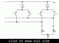
 

I'm not engaged in IC design and thus don't know all possible topologies. But the most popular current steering architecture known from literature uses PMOS differential pairs and won't work with NMOS transistors at all. See the schematic from the Analog Devices Data Conversion Handbook.


switch has the same type, as current source, because any current mirroring will means increasing of error and speed reduction. Choice between PMOS and NMOS is defined by design tradeoff
 

The "ground" for DACs/ADCs is usually a stable voltage derived from the bandgap. It is often not the digital ground.
In the case of the pure PMOS current steering DAC, it may be the lower DAC reference (buffered of course!).
The switch to be used depends on having the gate drive voltage being able to pass it's full voltage range with a decent Rds(on).
 

If you want a positive raw voltage / current then you would use PMOS. I've
done current steering DACs using NJFETs, back in the day, its negative
current was used against an inverting op amp virtual ground (with a trimmed
feedback resistor on the DAC chip) to get the positive output.
 

Actually, seems like the answer is that for PMOS current sources, an NMOS switch means that its Vgs depends on the output voltage since the source is the output. The PMOS switch would have the source at the current source output which is a constant voltage.
 

It's another way to explain, why an all PMOS design is suitable. I think however, that the current steering differential pair, which can be seen as a SPDT switch should be better understood as an active current source. It's high impedance output must be connected to the load.
 

In the current steering, it's easy to control the current because the Vgs only depend on the Vdd and Vbias. Another reason, actually the current steering differential pair with P structure has better output swing than the N structure.
 

Status
Not open for further replies.

Part and Inventory Search

Welcome to EDABoard.com

Sponsor

Back
Top