Continue to Site
Follow along with the video below to see how to install our site as a web app on your home screen.
Note: This feature may not be available in some browsers.
next	       count	      output
		120		1
+26		146		0
+26		172		1
+26		198		0
+26		224		1
+26		250		0
+26		276		1
+26		302		0
+26		328		1
+26		354		0
+26		380		1
		406		0
• After each burst which is between 6 cycles and 70 cycles a gap time of at least 10 cycles is necessary.
John
One idea for the led blinking would be to use a timer interrupt on compare match.
Depending on the timer frequency you can calculate the timer counts that represent that delay.
Alex
 I apologise for my lack of experience.
in my sketch?if (OCR1A>=406) { TCNT1=0; OCR1A=120;}
else if (OCR1A>=120) OCR1A+=26;
That's what I'm after Alex. Thank you!! I understand the logic of it, however I don't understand the code
I don't know how to implement this into my sketch
Can you point me to a tutorial which would show me, or show me yourself, how I would use in my sketch?
---------- Post added at 18:13 ---------- Previous post was at 18:03 ----------
I know how to say my sketch in english....
/* when timer count reaches 0 {turn on PWM sketch;}
turn off PWM sketch after x cycles;
at the end of PWM sketch, restart timer (restart cycle); */
// Timer/Counter 1 initialization
// Clock source: System Clock
// Clock value: 2000,000 kHz
// Mode: Normal top=FFFFh
// OC1A output: Toggle
// OC1B output: Discon.
// Noise Canceler: Off
// Input Capture on Falling Edge
// Timer 1 Overflow Interrupt: Off
// Input Capture Interrupt: Off
// Compare A Match Interrupt: On
// Compare B Match Interrupt: Off
OCR1AL=0x78;
OCR1AH=0x00;
TCCR1A=0x40;
TCCR1B=0x02;
TCNT1H=0x00;
TCNT1L=0x00;
ICR1H=0x00;
ICR1L=0x00;
OCR1BH=0x00;
OCR1BL=0x00;

// and then inside the compare matchA interrupt
if (OCR1A>=406) { TCNT1=0; OCR1A=120;}
else if (OCR1A>=120) OCR1A+=26;Hey John,
I've been thinking about my setup... Considering that the IR rec. output's a low whenever it gets a cycle of 38kHz, and that it cannot be held continuously low, won't I have trouble detecting when a count actually occurs? Because if the IR rec. will be outputting a HIGH every 6-70 cycles, then won't a count be recorded every 6-70 cycles?/
I am counting the number of people who use a bike path.. so they file up for meHow are you going to ensure single file for your beam-break method?
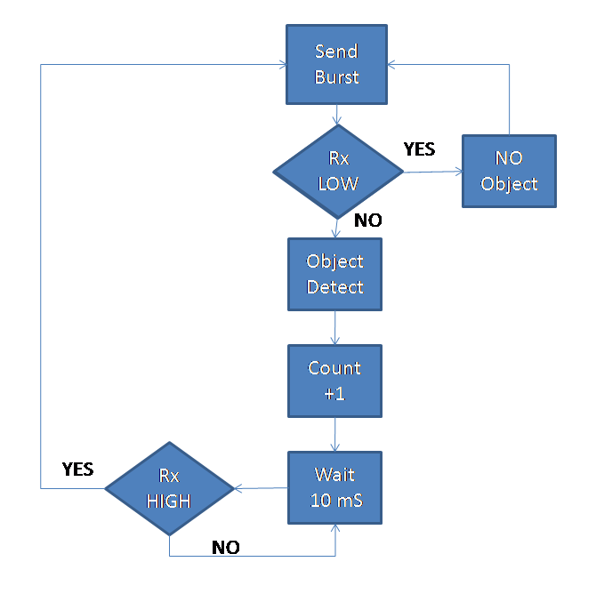
Second is a flow chart of what you want to do
After you get something working, then you can modify the 38 KHz carrier on/off spacings to improve it (if needed). I suspect that wouldn't be needed. Trying to improve on a system to get quicker detection before getting the basic system to work can lead to lots of frustration.
The problem is that I have no idea of what you can do with arduino and if you can write code in that level or if you can only use the provided arduino lib functions.
#include <TimerOne.h>

unsigned long now;
unsigned long then = 0;
unsigned long interval = 2500000;
unsigned long pwminterval = 5000000;

void setup(){
  pinMode(9, OUTPUT);
  Timer1.initialize();
  digitalWrite(13,HIGH);

}

void loop(){
  now = micros(); //variable to store the read value
  if (now - then > interval){
    Timer1.pwm(9,512,100000);}
  if (now - then > pwminterval){
    digitalWrite(9,LOW);
    then = now;
    }

}It is essentially a register (there are two available in the timer) that is loaded with a custom user value , when this value matches the value of the timer counter then depending on the settings you can get an interrupt and/or toggle/set/reset the compare output pin.
I'm using interrupt and toggle output, the output changes automatically and I use the interrupt to set the next match value.
micros() returns the number of microseconds since the Arduino board began running the current program
/* People counter sketch baby!
 */

// constants won't change. Used here to
// set pin numbers:
const int ledPin =  9;      // the number of the LED pin

// Variables will change:
int ledState = LOW;             // ledState used to set the LED
long previousMicros = 0;        // will store last time LED was updated
long then = 0; //stores value of now when it was last updated

// the follow variables is a long because the time, measured in miliseconds,
// will quickly become a bigger number than can be stored in an int.
long interval = 13 ;           // interval at which to blink (microseconds)
long pause = 520; // pause between pulsing
long pausepulse = 2080; //time from beginning of pause till end of pulsing

void setup() {
  // set the digital pin as output:
  pinMode(ledPin, OUTPUT);
}

void loop()
{
  // here is where you'd put code that needs to be running all the time.

  // check to see if it's time to blink the LED; that is, if the
  // difference between the current time and last time you blinked
  // the LED is bigger than the interval at which you want to
  // blink the LED.
  long now = micros();

  if (now - then >= pause && now - then <= pausepulse){
    unsigned long currentMicros = micros();

    if(currentMicros - previousMicros > interval) {
    // save the last time you blinked the LED
    previousMicros = currentMicros;

    // if the LED is off turn it on and vice-versa:
    if (ledState == LOW)
      ledState = HIGH;
    else
      ledState = LOW;

    // set the LED with the ledState of the variable:
    digitalWrite(ledPin, ledState);
    }}
  if (now - then >= pausepulse){
    then = now;}

  }