Continue to Site

Welcome to EDAboard.com

Welcome to our site! EDAboard.com is an international Electronics Discussion Forum focused on EDA software, circuits, schematics, books, theory, papers, asic, pld, 8051, DSP, Network, RF, Analog Design, PCB, Service Manuals... and a whole lot more! To participate you need to register. Registration is free. Click here to register now.

[SOLVED] PIC16F877A not working even after bieng programmed successfully using ICPROG

Status
Not open for further replies.

illegal121

Member level 2
Joined
Jun 20, 2011
Messages
49
Helped
1
Reputation
2
Reaction score
1
Trophy points
1,288
Location
Oman
Activity points
1,650
Hello Everyone....!

I am working on PIC16F877A I tried the following JDM programmer..
**broken link removed**
It works fine for my PIC with ICprog and ICprog verified the code successfully after programming the PIC16F877A
here is my code and it works best on proteus (simulation)..
Code:
unsigned int temp_res;
unsigned int temp_res1;
 char buf2[6];
 char buf[6];


 int i;
void main() {
 UART1_Init(9600);
 delay_ms(100);
   TRISA  = 0xFF;
  CMCON = 0x07;
  TRISA  = 0xFF;              // PORTA is input
  TRISC  = 0;                 // PORTC is output
  TRISB  = 0;                 // PORTB is output

  do {
    temp_res = ADC_Read(0);   // Get 10-bit results of AD conversion
    PORTB = temp_res;         // Send lower 8 bits to PORTB
    PORTC = temp_res >> 8;    // Send 2 most significant bits to RC1, RC0
    temp_res1=ADC_read(1);
   WordToStr(temp_res,buf2 );
    for(i = 0; i < 6; i++)
   {
      UART1_Write(buf2[i]);


      Delay_us(2);
     }
     UART1_Write(13);
       WordToStr(temp_res1,buf );
      for(i = 0; i < 6; i++)
   {

      UART1_Write(buf[i]);

      Delay_us(2);
     }
      }
     while(1);
              }
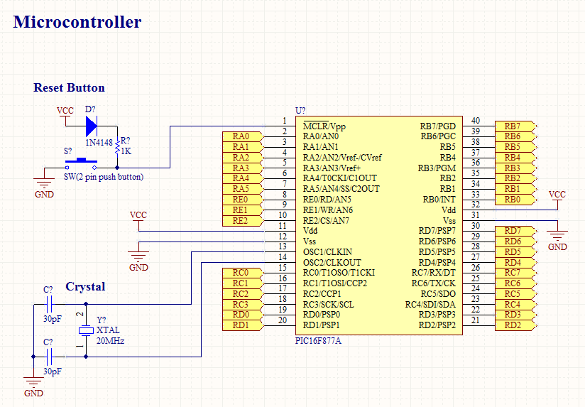
But my hardware circuitry is not working at all :( here is circuit I am using..

What is the problem .. If there is code problem then why it works on Proteus..
But what I think is there is hardware problem my PIC no. is PIC16F877A-I/P (1114j9b)
Please Help... !
thank u ..
 

What compiler are you using?

The program failure could be a result of several issues. However, I need to see the entire program listing, so please post it in its entirety.

BigDog
 

Many times the problem is the configuration bits settings,check if you have set the configuration bits properly.You will find all the details in your datasheet.In your external reset circuit you don't need the diode IN4148 just pull up the 1K resistor to Vcc(in CMOS circuitry we dont use the term Vcc rather we use Vdd) and normally I use a 10K pull up resistor for reset rather 1K.You are using a 20Mhz crystal, so your configuration bits must be set for HS (High Speed Crystal/Resonator).Your mcu consist of two Vdd and Vss,you should power them both.

You can set your configuration bits from code or from ICprog.

Else their may be some problem in your code,so as its already have been said provide us with the info about your development platform.

Good Luck
 

Thank u For your Time...
I am using MikroC compiler
@bigdogguru
What do u mean by "in its entirety" ..? this is my full complete code so far ..
@debjit625
Yes I have tried all things :( I mean changing different configuration setting and HS etc.. but no result..


(As I had searched out in Google that many PIC cant properly work at 20Mhz oscillator they need 4Mhz oscillator , true ... ? :S )
Thank u for the help...
 

I am using MikroC compiler
@bigdogguru
What do u mean by "in its entirety" ..? this is my full complete code so far ..
(As I had searched out in Google that many PIC cant properly work at 20Mhz oscillator they need 4Mhz oscillator , true ... ? :S )

If you were not using MikroC I was referring to the subroutines used.

Yes, the PIC16F877A can operate without issues at 20MHz, however the PIC16LF877A is limited to 10MHz.

You need to use the HS setting when running a system clock at 20MHz, the 33pF capacitors you are using are at the edge of the acceptable range. You may want to switch them out for 22pF capacitors.

Have you disable the watchdog timer, WDT, in the configuration settings? Make sure you set all code protection off, CPD, WRT, CP bits.

Have you verified the HEX file has been successfully programmed into the PIC.

Have you or can you run in debugger mode and step through the programming during execution?

I'm still checking other possible issues.

BigDog
 

bet your problem is about the configuration bits issues .. check your compiler setting go to project settings and look for the config bits cifiguration

vareh.png
 
Yes , As you said about all configuration setting i keep the same configurations..
and ICprog also verified my code successfully after programming ..
you are talking about debugger mode in ICprog software...?
 

no... can you post here your config settings? look at the image above something like that
 

Yes , As you said about all configuration setting i keep the same configurations..

What are your exact configuration settings?

and ICprog also verified my code successfully after programming ..

Good that is one issue out of the way.

you are talking about debugger mode in ICprog software...?

Yes, if it supports it. I not familiar with the ICProg software interface.

Have you tried loading a simple program which flashes an LED? This will eliminate the issue of your system clock functioning correctly.

BigDog
 

@romel_emperado

thanks for the reply...
yes I have already configured this window too..
 

Attachments

  • Mikro.bmp
    2 MB · Views: 147

Your configuration bits settings look correct.

Have you set your system clock rate in MikroC to 20MHz?

BigDog
 

try to disable the LVP(low voltage programming).

I have a experience with that also but I dont know my PIC did not work because of that.. hehee

why is it bigdogguro ?? hihi

---------- Post added at 03:52 ---------- Previous post was at 03:51 ----------

if I were you try making a blinking led program and test it...
 

yes .. You are talking about this one rite... ?
 

Attachments

  • Mikro.bmp
    2 MB · Views: 123

yes .. You are talking about this one rite... ?

Yes, that is correct.

I believe the next course of action should be to load a simple LED blinker program.

Doing so would eliminate the clock failure possibility.

BigDog
 
Add this code above while(1);

something like this and let us know if PORTB blinks..

PHP:
PORTB = ~PORTB;
while(1);


---------- Post added at 04:04 ---------- Previous post was at 04:01 ----------

we have also the same experience with this PIC :) :) I just learned also about PIC... <3

try also disabling the LVP I dont know but my PIC before doesn't work if that is enabled ... I dont know :) :) :-D
 

try to disable the LVP(low voltage programming).

I have a experience with that also but I dont know my PIC did not work because of that.. hehee

why is it bigdogguro ??

It could possibly be due to the programmer you are using. I do not have an issue with it and the ICD2 or ICD3.

Are you using a ICProg as well Romel?

BigDog
 
hey see whats happening .. I make a program which send high then low for 6 times on port B..
Without oscillator it is not working at all .. When i connect oscillator , during connecting time LEDes blinked very sharply but after that some are blinking and some are not (still OSC is connected)..
 

hey see whats happening .. I make a program which send high then low for 6 times on port B..
Without oscillator it is not working at all .. When i connect oscillator , during connecting time LEDes blinked very sharply but after that some are blinking and some are not (still OSC is connected)..

this is a clock issue ;; :)

---------- Post added at 04:11 ---------- Previous post was at 04:10 ----------

I dont know but that's why I dont use mickro C.. try to hardcode the config bits
 

hey see whats happening .. I make a program which send high then low for 6 times on port B..
Without oscillator it is not working at all .. When i connect oscillator , during connecting time LEDes blinked very sharply but after that some are blinking and some are not (still OSC is connected)..

You may not have all the pins of PORTB configured properly for output.

At least you know you have a system clock.

Are you getting no output at all on the serial port connect to the PC?

If not let's concentrate on getting the UART functioning next without any other peripherals.

Just send a simple string like "Hello" to you PC.

BigDog
 
It could possibly be due to the programmer you are using. I do not have an issue with it and the ICD2 or ICD3.

Are you using a ICProg as well Romel?

BigDog

Im using PICgm and it works very well with my PIC16/18 PICs.. :)

and also I used this yesterday with my tachometer using pic16f690 and it works very well

**broken link removed**
 

Status
Not open for further replies.

Part and Inventory Search

Welcome to EDABoard.com

Sponsor

Back
Top