Continue to Site

Welcome to EDAboard.com

Welcome to our site! EDAboard.com is an international Electronics Discussion Forum focused on EDA software, circuits, schematics, books, theory, papers, asic, pld, 8051, DSP, Network, RF, Analog Design, PCB, Service Manuals... and a whole lot more! To participate you need to register. Registration is free. Click here to register now.

2 channel IR remote control circuit

Status
Not open for further replies.

aliraza786

Full Member level 4
Joined
Nov 10, 2009
Messages
210
Helped
14
Reputation
28
Reaction score
14
Trophy points
1,298
Location
Lahore, Pakistan, Pakistan
Activity points
2,914
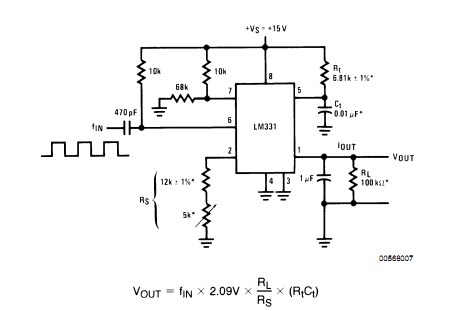
hello i wana discuss my circuit design with you people..if i convert the frequency to voltage then comapre the voltage to do diffrennt task by comparator is it correct design. which frequency to vilatge convertor should i use..? like lm331 is one of the ic used for this purpose..
 

Re: 2 chanel ir remote controle circuit

Why do you want to convert frequency to voltage? What are you going to do with it? If you convert to voltage, of course, you can compare it, but we need to know why you want to convert it. LM331 is a voltage to frequency converter, not frequency to voltage converter. A common frequency to voltage converter is LM2917. Datasheet : www.national.com/pf/LM/LM2917.html

Hope this helps.
Tahmid.
 

Re: 2 chanel ir remote controle circuit

bceuse i have worked a lot on filters but coudnt succed in making good filter for square wave and also i have no idea how can i use 8051 timer to count pulses in one second.thats why i am using this frequency to voltage convertor. check this circuit is it wrong..??
Frequency to voltage converter using LM331 - Electronic Circuits and Diagram-Electronics Projects and Design
ya you are right Lm331 is volatge to frequency convertor datasheet shows this but i see this circuits thats why i ask..
 

Re: 2 chanel ir remote controle circuit

If you look at the comments, one of them said that he got the circuit working.

---------- Post added at 16:39 ---------- Previous post was at 16:36 ----------

Download the LM331 datasheet:
www.national.com/ds/LM/LM231.pdf
There are quite a few such circuits shown.

This is the circuit from the datasheet. The value of the capacitor between Iout and ground is different from the circuit you had posted:
12_1313663969.png


Hope this helps.
Tahmid.
 

Re: 2 chanel ir remote controle circuit

thnks tahmid my problem is solved eror was there in the value of the output capacitor it should be 1uf instead of 100pf...
check the pics with 1uf capacitor and 100pf capacitor...i am shocked to see the diffrecne ....
c.jpg

and after correction by use..
b.jpg

thnku very much...i wana ask one thing more output voltage depend upoon the intensity of frequency or it is independant of the input frequency voltage..becuse when i transmit frequency from ir diode to ir reciver then the distance is not fixed it may vary from person to person who uses this system...thnks is advance
 

Re: 2 chanel ir remote controle circuit

thnks tahmid my problem is solved eror was there in the value of the output capacitor it should be 1uf instead of 100pf...
check the pics with 1uf capacitor and 100pf capacitor...i am shocked to see the diffrecne ....
View attachment 60361

and after correction by use..
View attachment 60362

thnku very much...i wana ask one thing more output voltage depend upoon the intensity of frequency or it is independant of the input frequency voltage..becuse when i transmit frequency from ir diode to ir reciver then the distance is not fixed it may vary from person to person who uses this system...thnks is advance
 

Re: 2 chanel ir remote controle circuit

When we transmit signals from the IR LED to the IR receiver, usually we keep the frequency constant and carry out modulation depending on the protocol. You can read about these protocols here:

SB-Projects: IR Remote Control

Hope this helps.
Tahmid.
 
Re: 2 chanel ir remote controle circuit

its just a basic i have to write a long anf complex code to transmit and decode the signal but i dont want to go in more depth of this remote controle becuse it is just a small part of my project ....thnks TAHMID
 

Re: 2 chanel ir remote controle circuit

What is your project? Why don't you use SIRC or RC5 and modify an existing code from the internet? There are many for PIC and AVR, and you should easily be able to find some for 8051.

Hope this helps.
Tahmid.
 

Re: 2 chanel ir remote controle circuit

ok i try can you give me some link for a c code of remote controle for 8051..?? my project is mobile intefacing with 8051.

---------- Post added at 14:29 ---------- Previous post was at 14:00 ----------

TAHMID you do work on Lm567 tone decoder..?
 

53_1314251926.gif

i have to design a circuit name 2 channle ir remote controle so i convert the frequency to voltage through LM331 and compre the out put voltage by comparator everything works fine but the problem is when i connect the 555 output pin to lm331 input pin everything works fine but when i transmit the frequnecy through ir led and attach ir reciver at the lm331 frequency input then nothing happpened this means that the problem is with ir reciver..........i use universal ir reciver see the picture attach.......i dnt know the error is due to the frequency response
 

As an obvious assumption, the circuit may be saturated by ambient light. In addition, the response will be in fact rather slow.

I generally doubt that DC coupled receiver circuits will allow reliable operation of a remote controller. I suggest to review the operation principle of industry standard (38 kHz) remote control receivers.
 

are u talking about TSOP1238 or TSOP 1738 these are the reciver of 38khz u mean to say i send modulated 38khz wave to this reciver to make two chnnel.....??
 

I mainly wanted to mention the 38 kHz technology as an example of a good designed remote control. If your circuit doesn't work, it's worth to consider what they do different.

Of course, utilizing 38 kHz receivers is always on option to build a remote control. A multi-channel system would usually refer to unique pulse patterns, like e.g. the popular RC5 standard. A two channel system can use very simple waveforms to distinguish between the channels.
 

are u talking about TSOP1238 or TSOP 1738 these are the reciver of 38khz u mean to say i send modulated 38khz wave to this reciver to make two chnnel.....??

Yea, like them. You can also use the PNA4602 which is quite popular as well. For 2 channel remote, you need some form of modulation to differentiate between the two channels. If you use a protocol like SIRC (Sony's) or RC5 (Philips'), you can follow their protocol from the link I mentioned above. This would also let you use a Sony or Philips remote. However, you can set up your own protocol by having two different types of waveforms, as all you need is control over 2 channels. If, however, you plan to extend this over to something larger, then it would be wiser to use RC5 or SIRC or another protocol.

Hope this helps.
Tahmid.
 
Tamid can you suggest me a site of can you give me sample code for modulation ans demodulation in c....i need it badly........thnks...any help will be highly appreciated...thnks
 

Status
Not open for further replies.

Similar threads

Part and Inventory Search

Welcome to EDABoard.com

Sponsor

Back
Top