Vermes
Advanced Member level 4
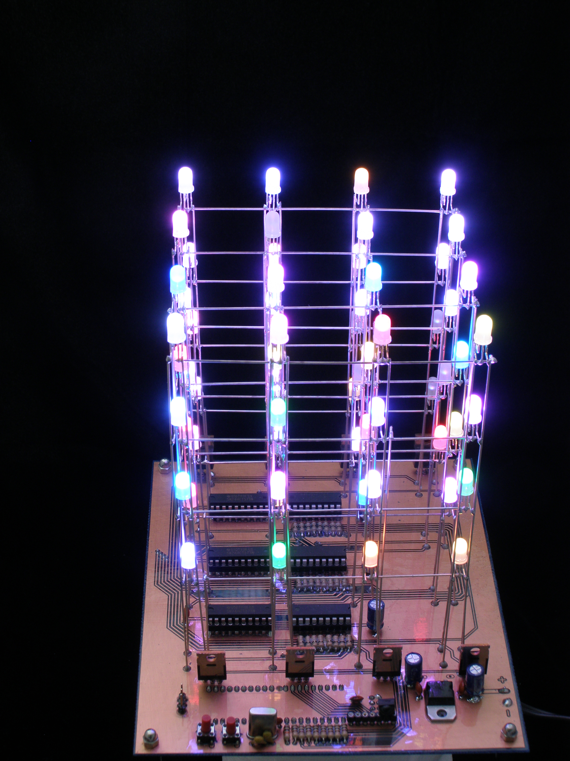
This device is a 3D led cube. The main idea was to connect all the LEDs to the board without many cables.
The schema:
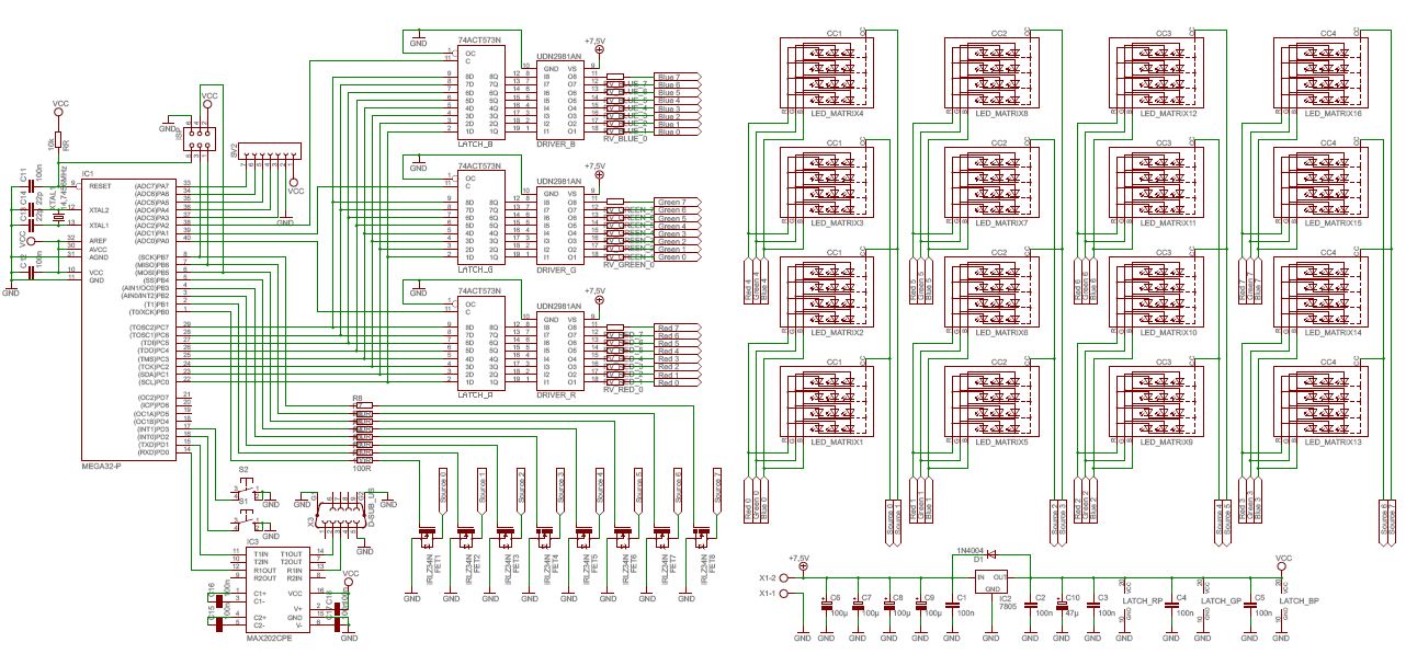
(one of attachments is a TTL schema)
The core of the device is Atmega32 with a clock of 14,745 MHz. The LED matrix is made of RGB LED with a common cathode. The cathodes are steered by IRLZ34N transistors when anodes are steered by 74ACT573 microchip with UDN2981 driver. The processor sets the bit value on C socket, and next blocks the change of it by setting clk signal on one of 3 ports A0-A3. Displaying the chosen sequence is followed by setting a Mosfet transistor responsible for the given branch.
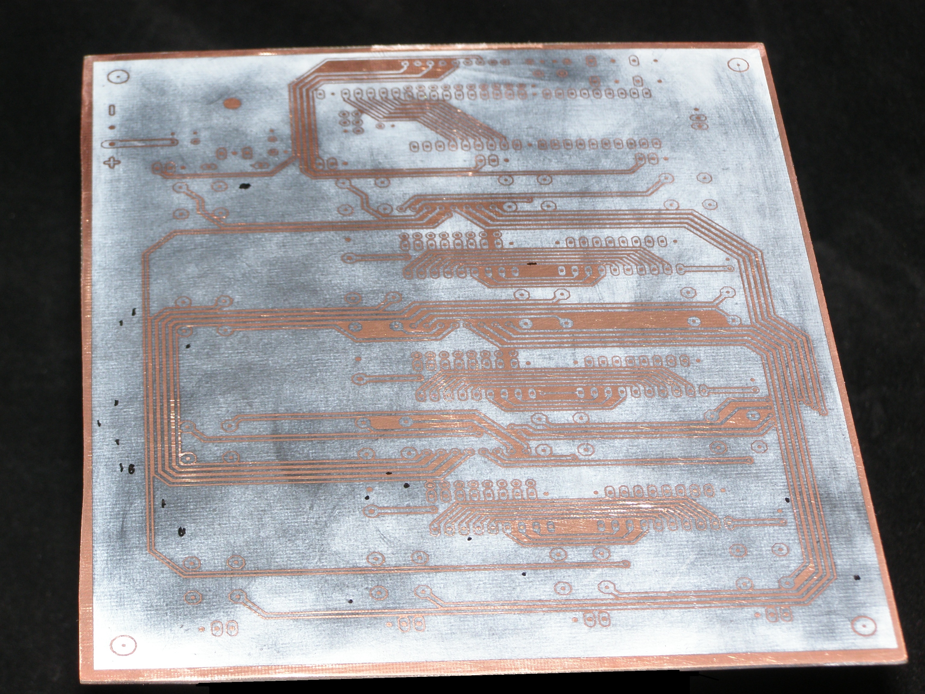
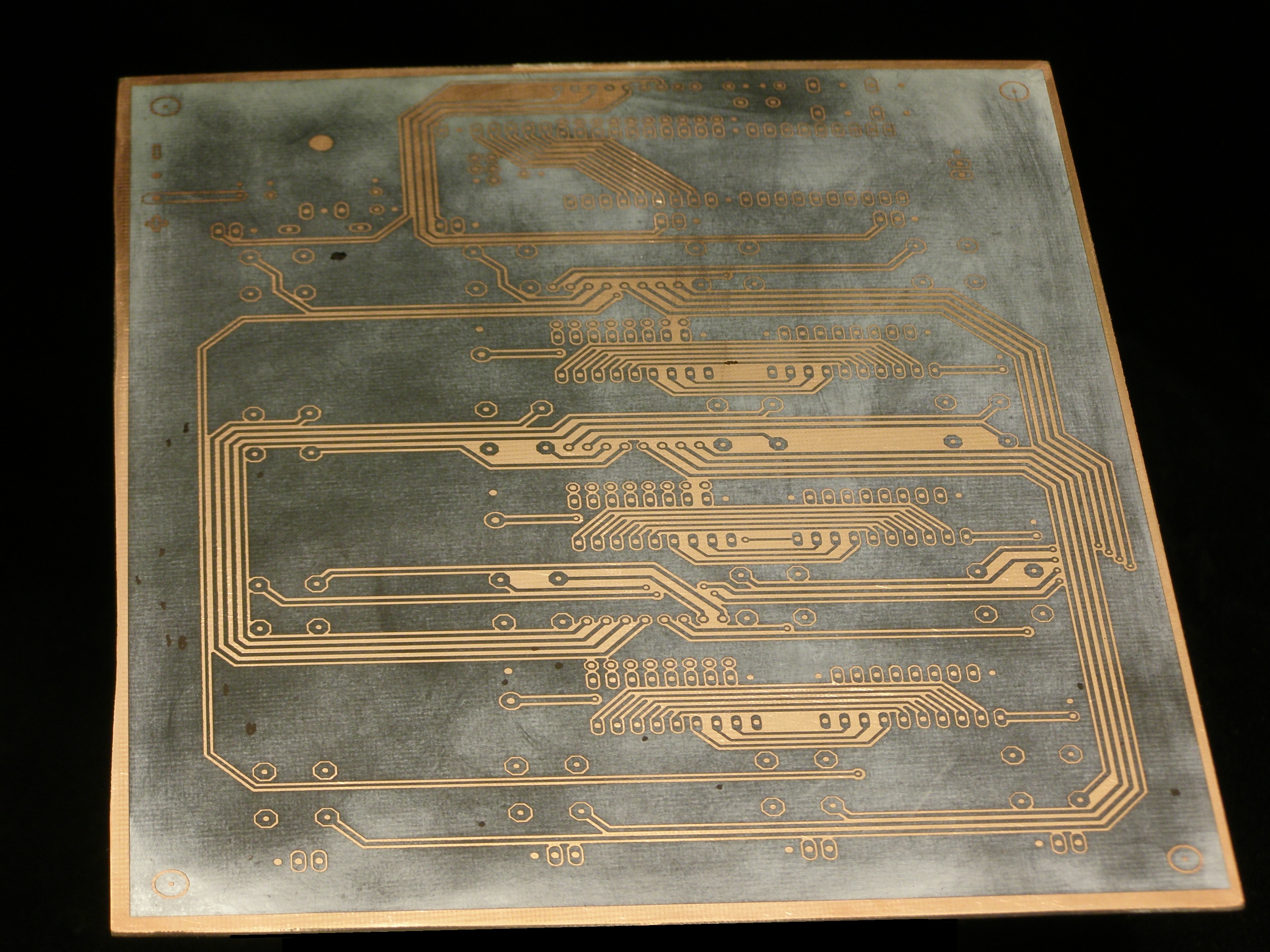
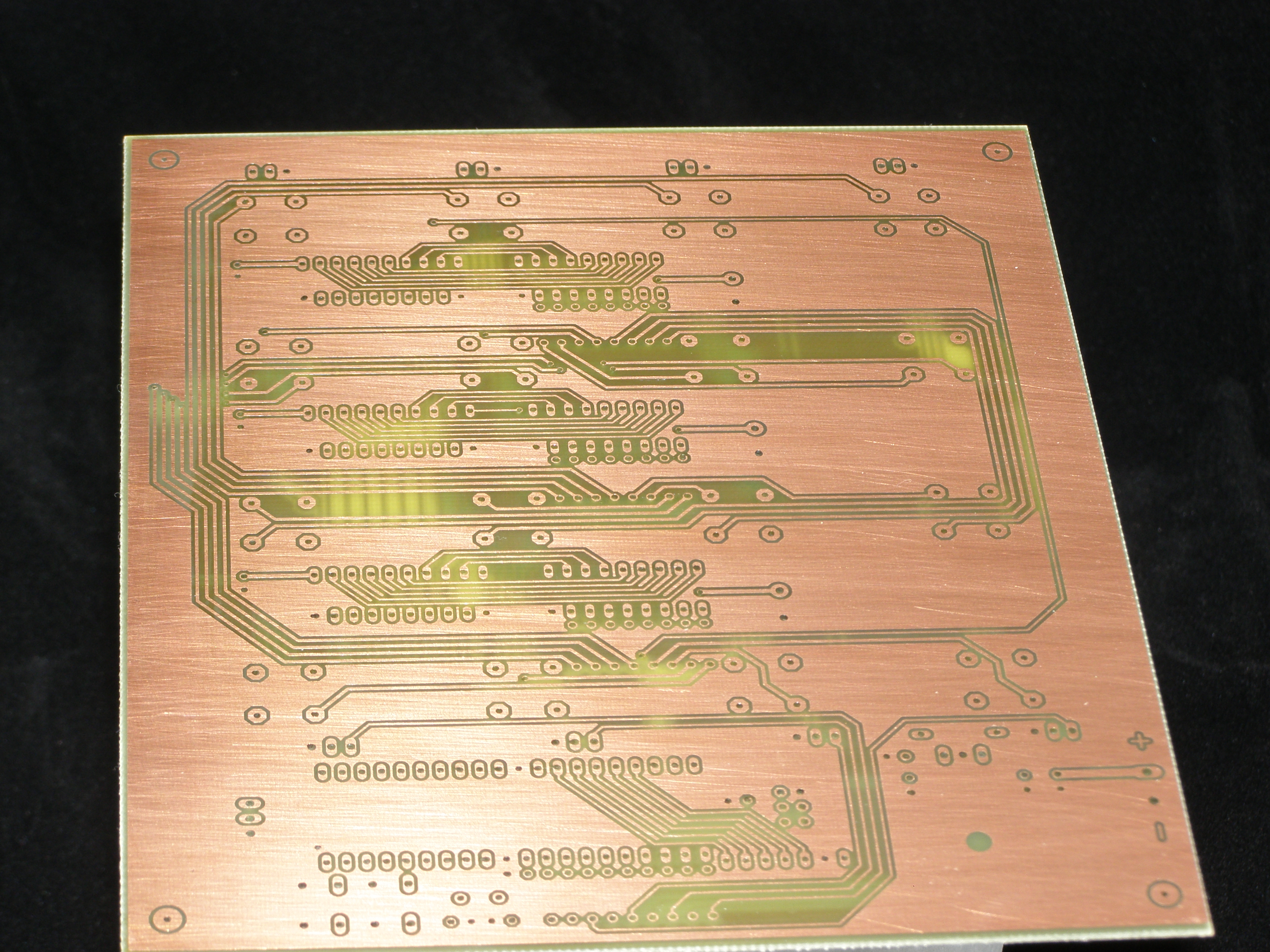
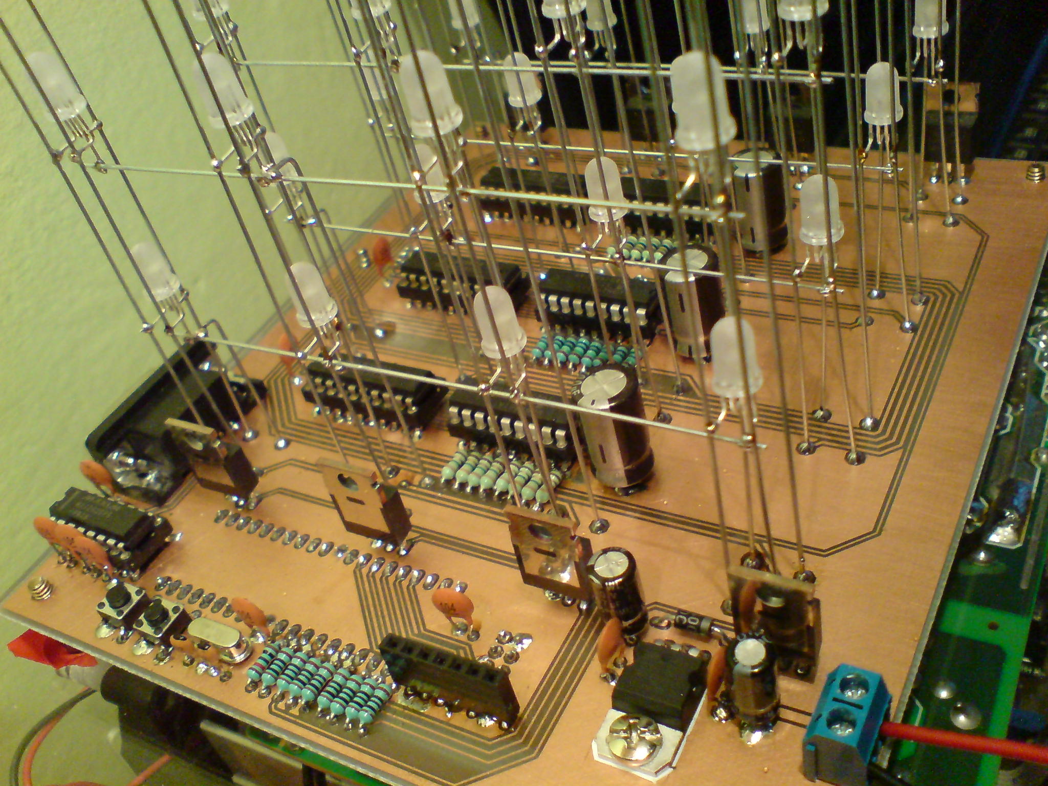
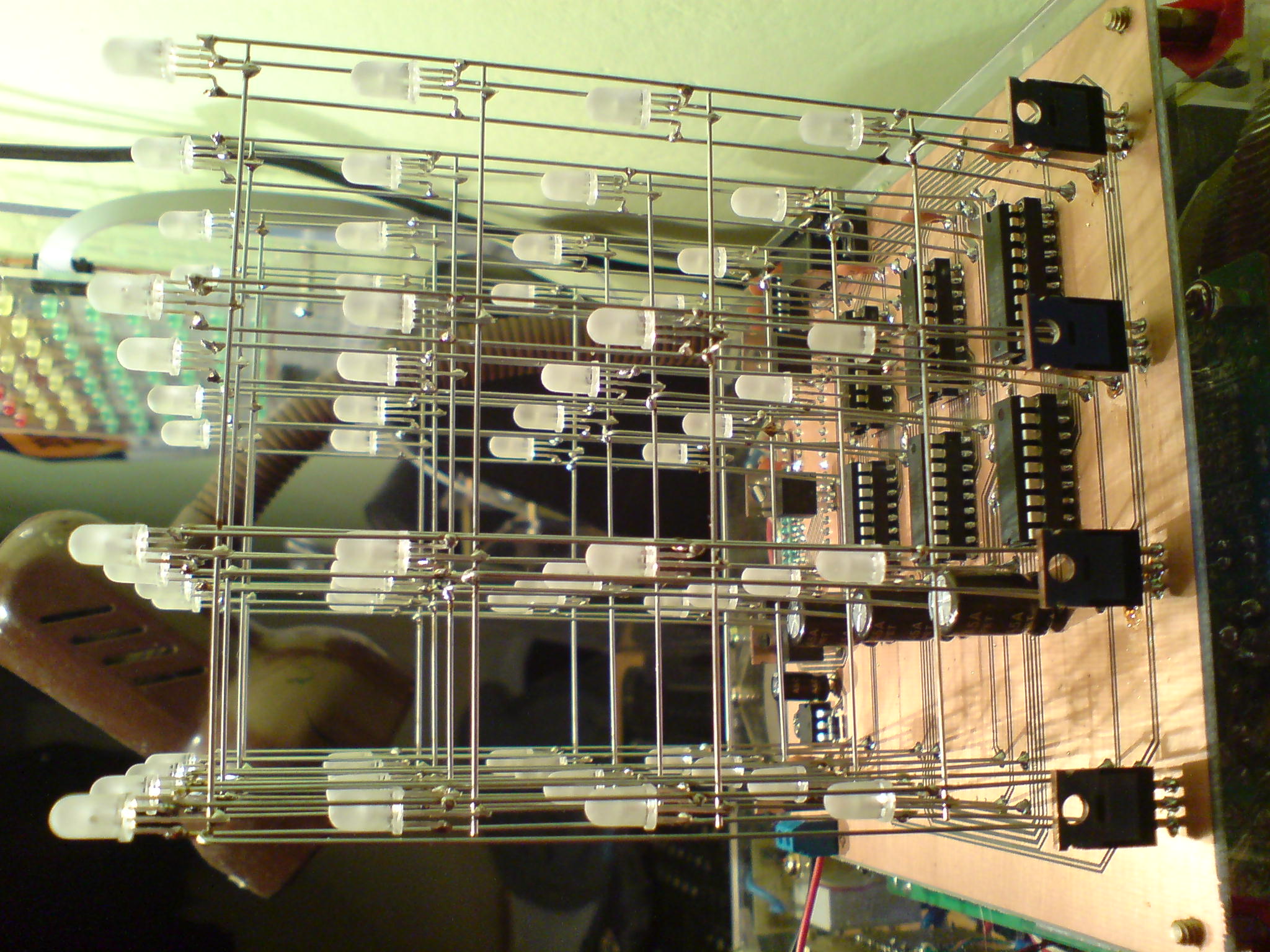
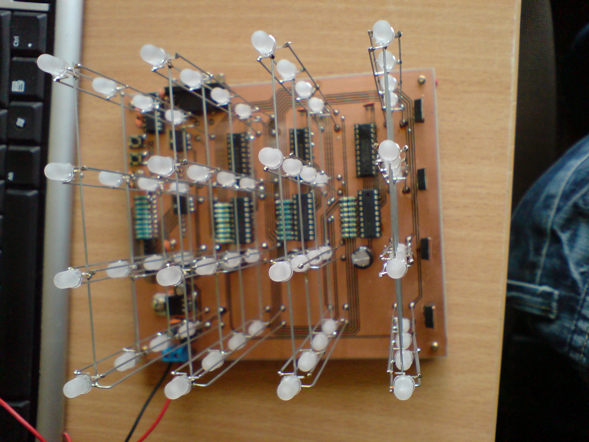
Realization:
The board is bilateral and quite big therefore it isn't easy to make.
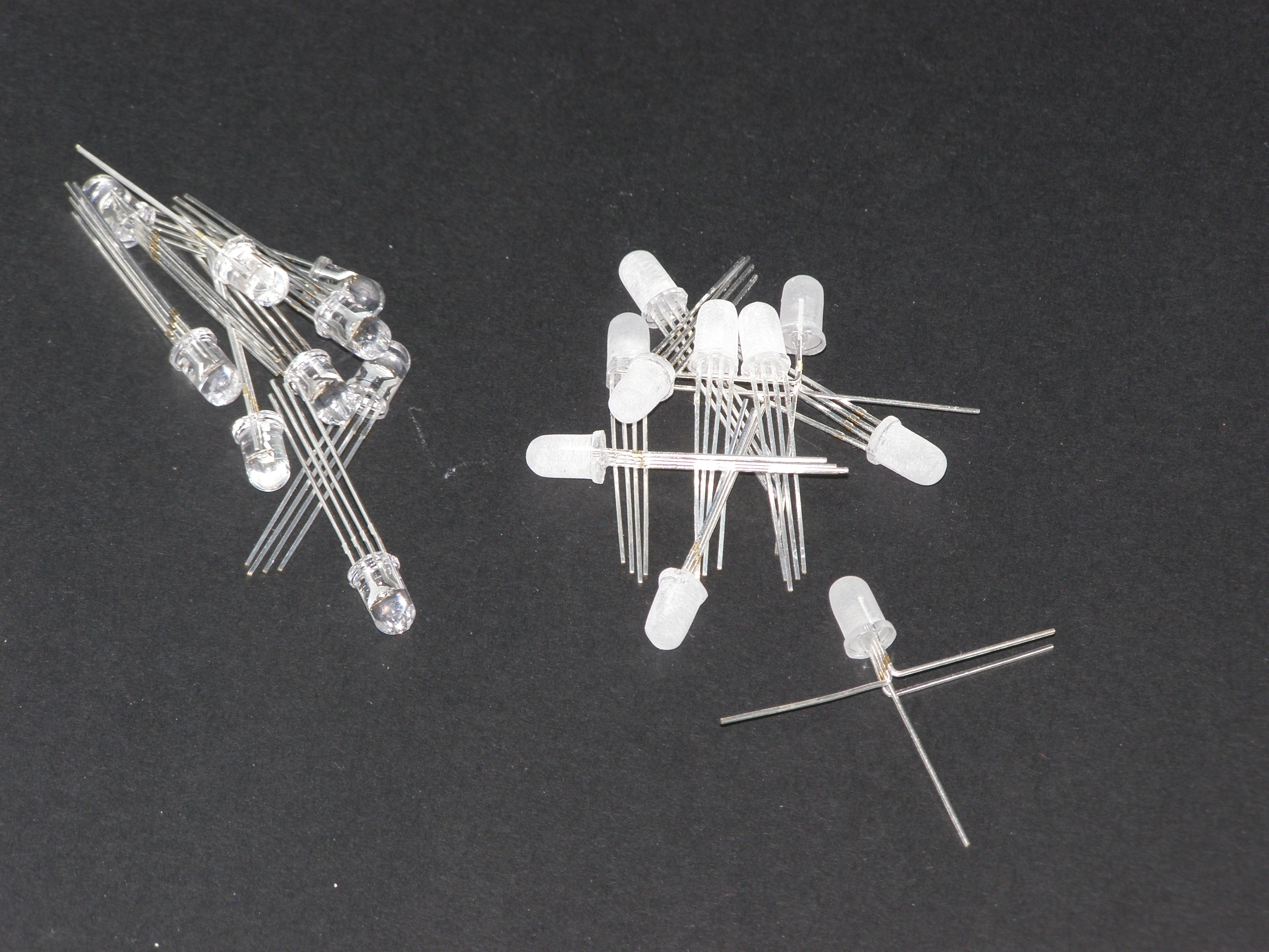
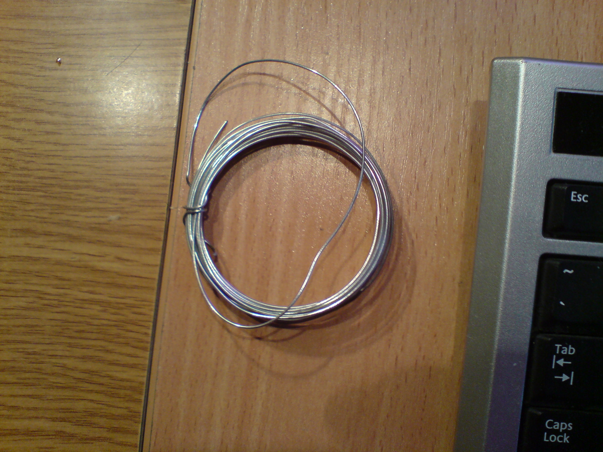
The next difficulty was to make a straight and good looking LED cube. For making that, a plexi board with holes was made. When the cube was designed, there were only LEDs with transparent housings, therefore all the leds were sanded with fine-grained sandpaper. The next problem was to get the LEDs cables to fit the right length (5mm). A 0.8 mm wire was used.
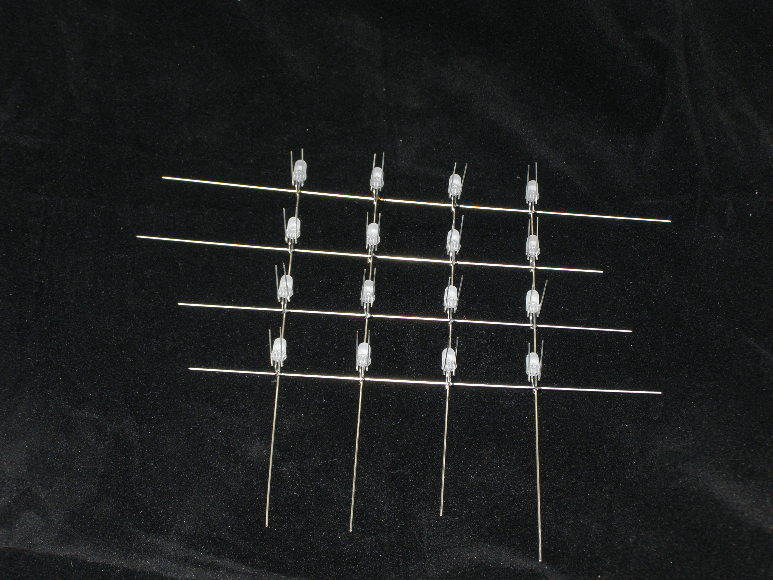
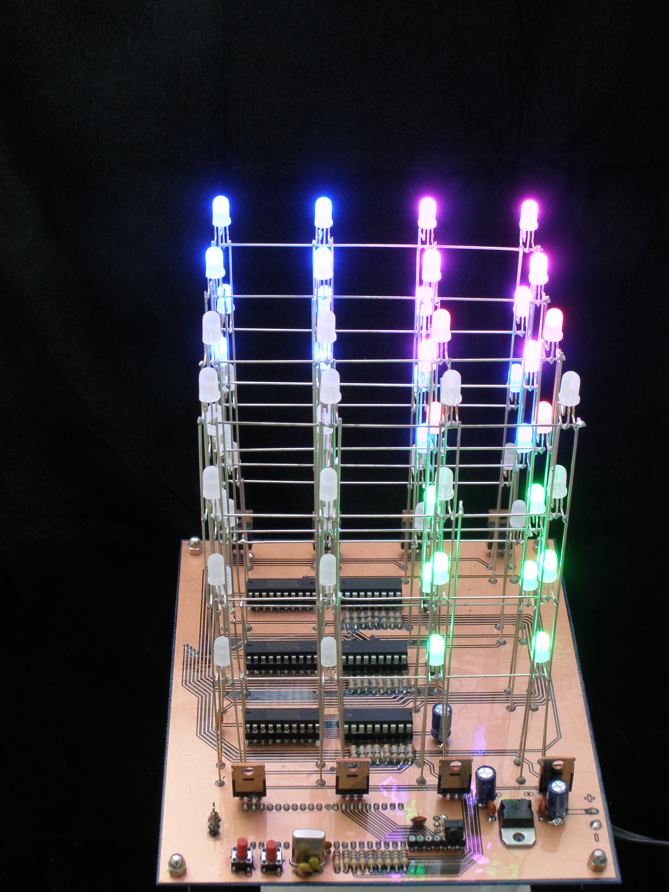
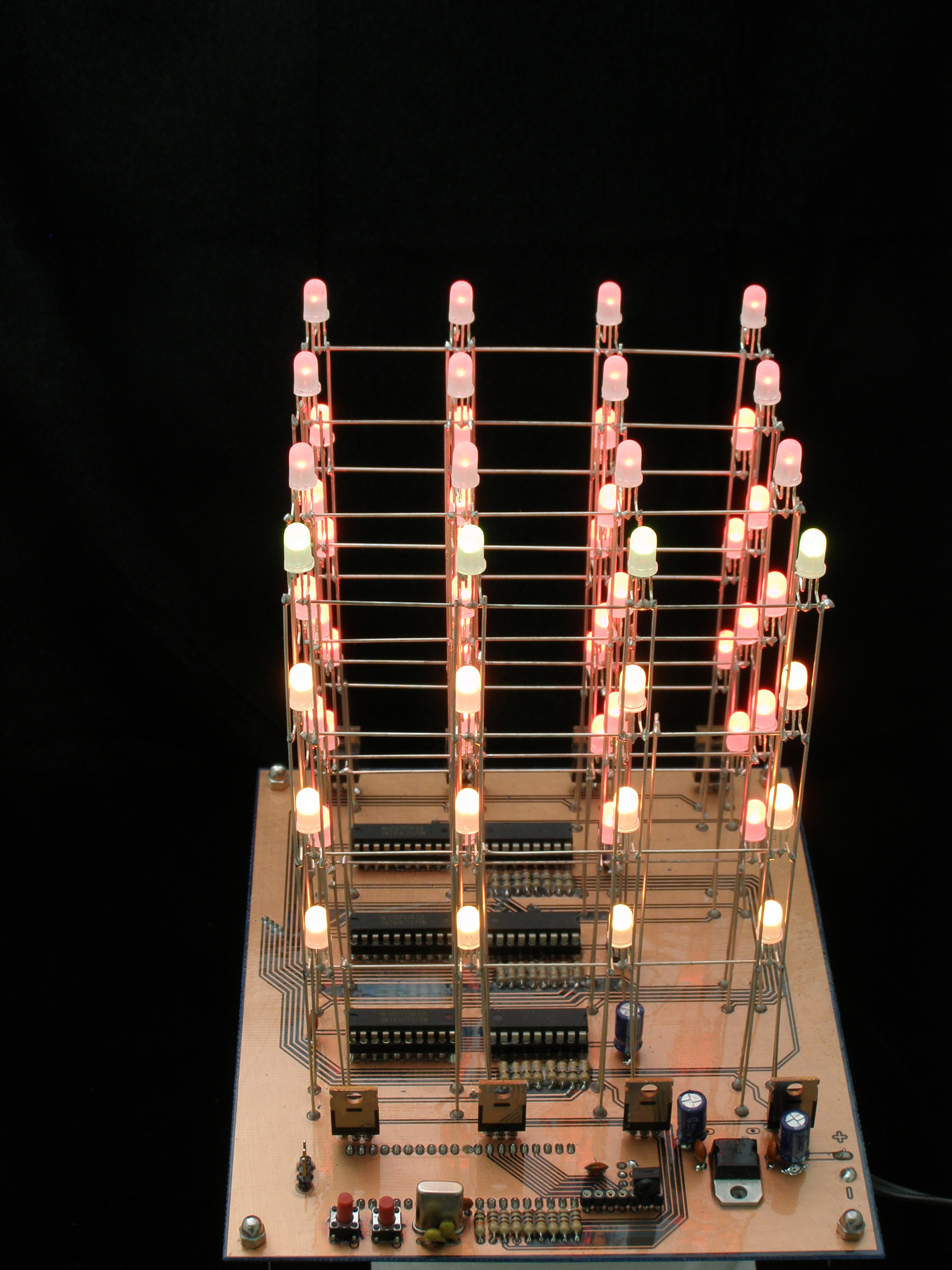
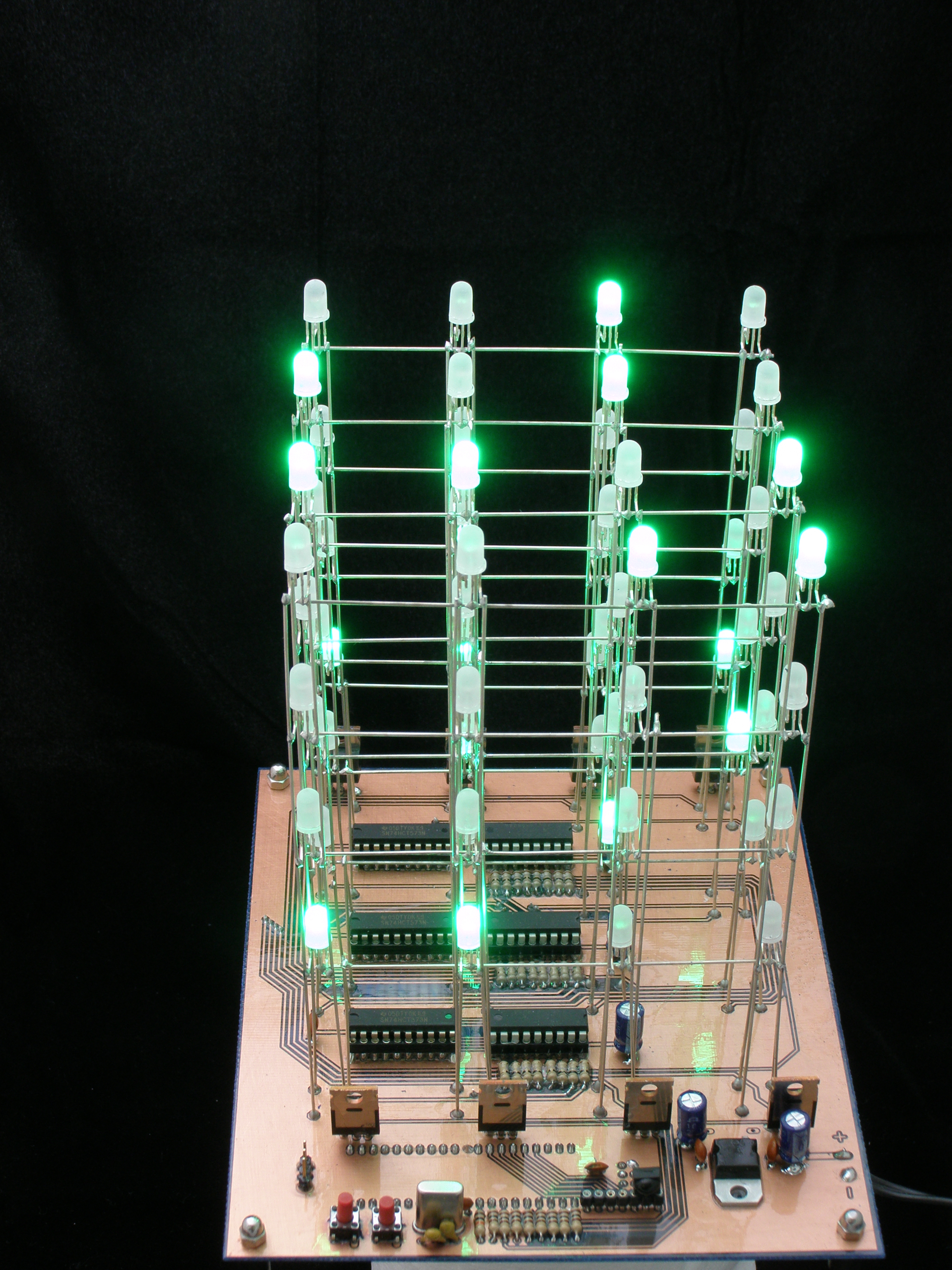
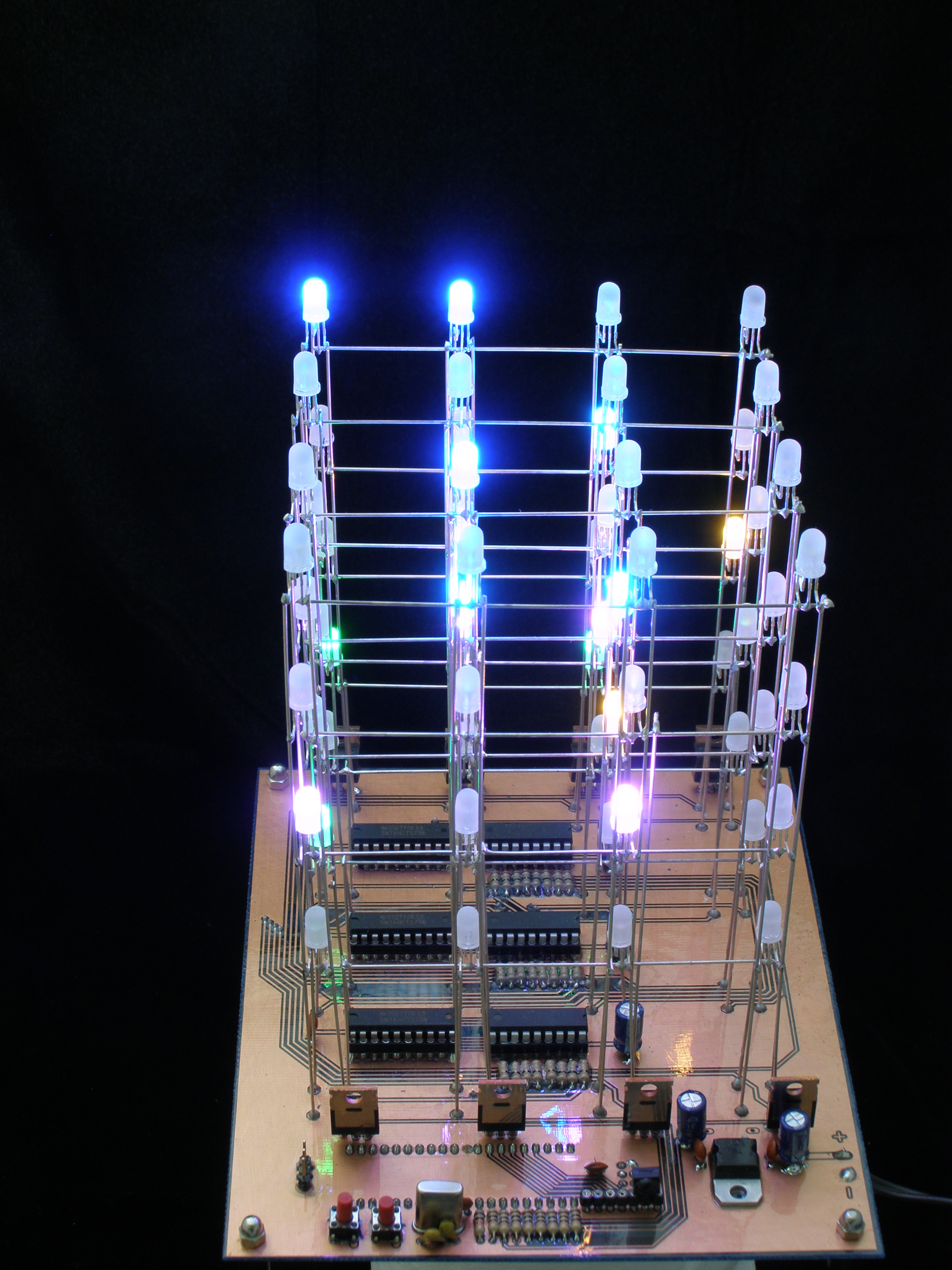
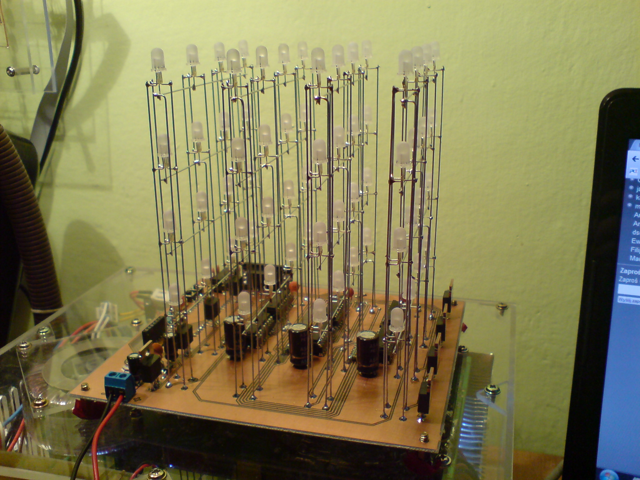
Final result:


Programming:
The main program is written in Bascom AVR. Steering based on 74HC573 (D flip-flops).
The program has 3 modes:
- The chosen animation mode – the animation is played still around. The mode can be chosen by using a button on the board or with a remote control sending an appropriate code in RC5 standard.
- The presentation mode – (mode appears in the film) after the animation, the program goes to the next. It can be chosen by pressing the second button on the board or similar with the remote control.
- The “light” mode – this mode can be only called with the remote control. All the LEDs light in one of the 7 colors.
Additives and remarks:
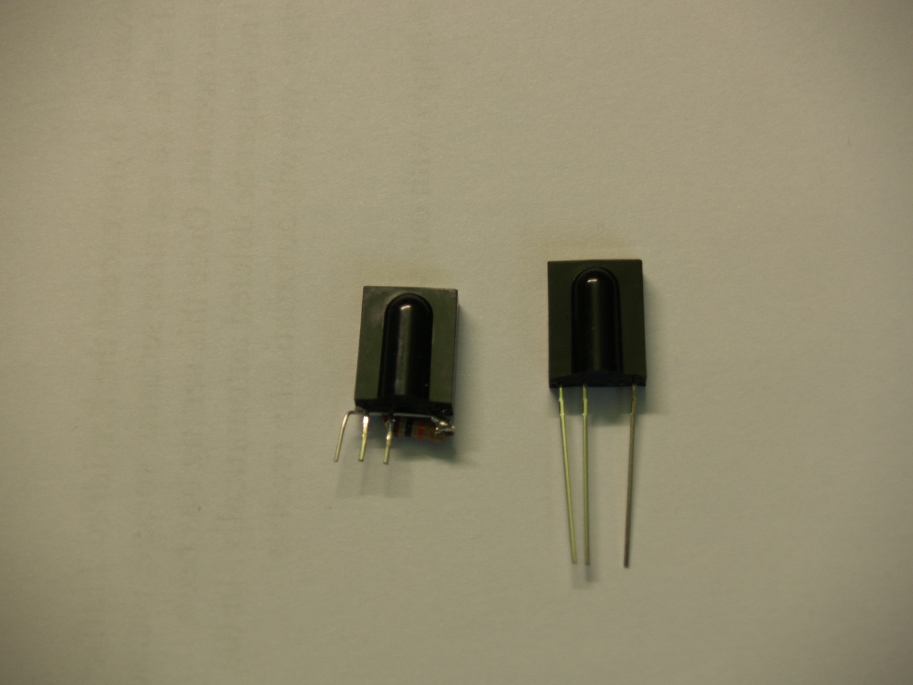
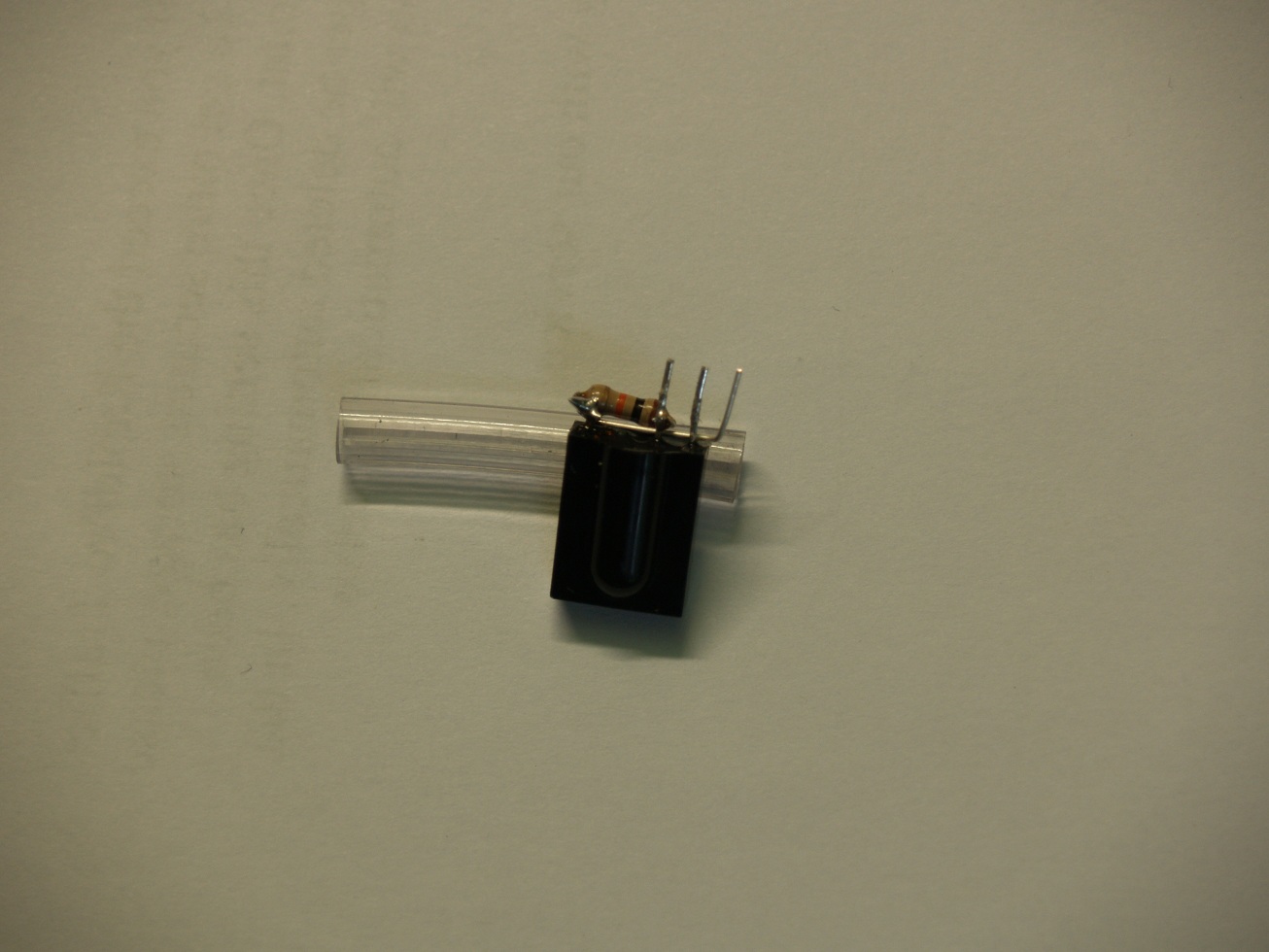
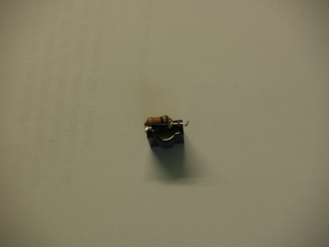
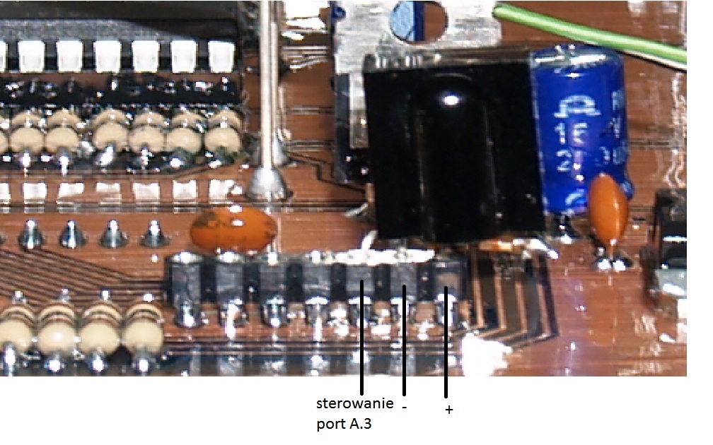
RC5 steering - example on IR5440 (36kHz)
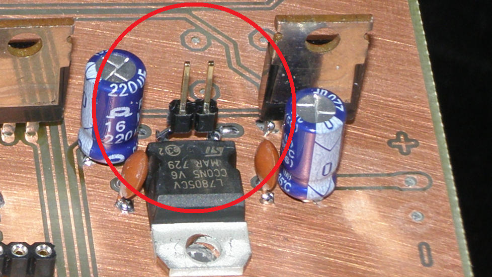
Power supply:
The cube can be powered by 7.5V, but it can be lower. There are two solutions:
- Voltage of 5V – because of the 7805 stabilizer, a jumper must be applied (it's viewed in the second picture)
- A board with a stabilizer with adjustable output voltage (maximum intensity 1.5A)
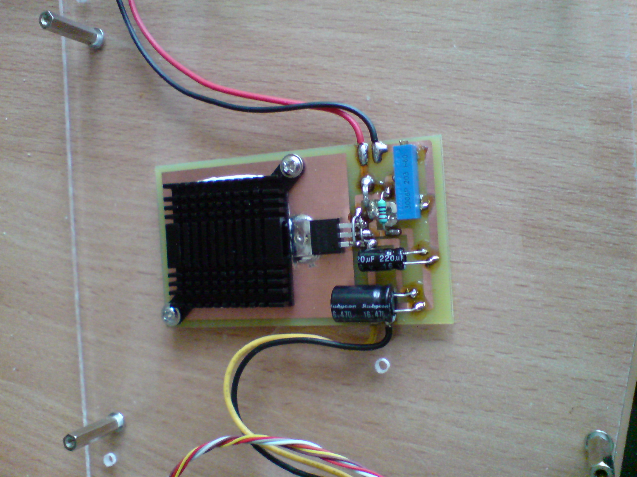
The board power consumption powered by 12V on the regulator and 6.5V on output takes 0.05 to 0.6 amperes (depending on the animation).
Link to original thread - LED CUBE 4x4x4