yassin.kraouch
Advanced Member level 2
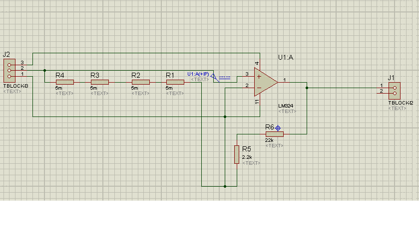
i have a problem with my circuit : i have to calculate the current throught the shunt resistor ( each shunt have a value of 5 m ohm, so the value is 20 mohm ) the current is 4A and the voltage is 80 mV and the gain is 10, the pin 1 of J2 is the GND, the pin 3 of J2 is VCC, the pin 2 is the input of the voltage to amplifie, when i test my circuit i have no voltage that has been amlpified, have you an idea about this ?