Welcome to our site! EDAboard.com is an international Electronics Discussion Forum focused on EDA software, circuits, schematics, books, theory, papers, asic, pld, 8051, DSP, Network, RF, Analog Design, PCB, Service Manuals... and a whole lot more! To participate you need to register. Registration is free. Click here to register now.
First you create the test bench in the same proyect where you VHDL document are.
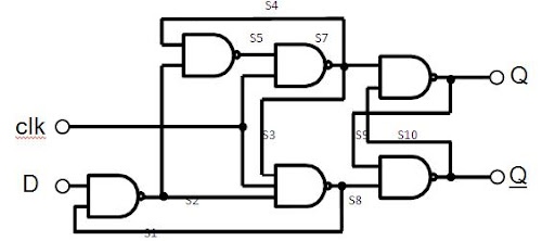
Second, You need to visualise the code to test as a black box, you need to know all the inputs and outputs.
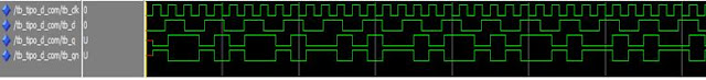
Finally you create the stimulus signals for the inputs and you will have the output.
----------------------------------------------------------------------------------
-- Company: ITESO
-- Engineer: David Rios Y Valles ROdirguez
--
-- Create Date: 00:37:51 04/11/2009
-- Description: Descripcion en forma de compuertas de un latch tipo D.
--
----------------------------------------------------------------------------------
library IEEE;
use IEEE.STD_LOGIC_1164.ALL;
use IEEE.STD_LOGIC_ARITH.ALL;
use IEEE.STD_LOGIC_UNSIGNED.ALL;
entity tipo_d_com is
Port ( clk : in STD_LOGIC;
d : in STD_LOGIC;
q : out STD_LOGIC;
qn : out STD_LOGIC);
end tipo_d_com;
architecture Behavioral of tipo_d_com is
signal s1: std_logic;
signal s2: std_logic;
signal s3: std_logic;
signal s4: std_logic;
signal s5: std_logic;
signal s6: std_logic;
signal s7: std_logic;
signal s8: std_logic;
signal s9: std_logic;
signal s10: std_logic;
signal sq: std_logic;
signal sqn: std_logic;
begin
s2<= D NAND S1;
S8<=not( s2 and clk and s3);
s5<=s6 nand s4;
s7<= clk nand s5;
s4<=s7;-------
s3<=s7;-------
s6<=s2;-------
s1<=s8;-------
Now as we can see in the picture, we need only two signals , D and CLK.that means that we only need to create two input signals, in test bench VHLD code, you can use many commands like delays, etc..
For the test bench I created the following code.
--------------------------------------------------------------------------------
-- Company: ITESO
-- Engineer: David Rios Y Valles Rodriguez
--
-- Create Date: 11:14:30 04/11/2009
-- Design Name:
-- Module Name: C:/dig_david/tipo_d_com/tb_tipo_d_com.vhd
-- Project Name: tipo_d_com
-- Target Device:
-- Tool versions:
-- Description: Test bench de el Flip- Flop tipo D con
--------------------------------------------------------------------------------
LIBRARY ieee;
USE ieee.std_logic_1164.ALL;
USE ieee.std_logic_unsigned.all;
USE ieee.numeric_std.ALL;
ENTITY tb_tipo_d_com IS
END tb_tipo_d_com;
ARCHITECTURE behavior OF tb_tipo_d_com IS
-- Component Declaration for the Unit Under Test (UUT)
COMPONENT tipo_d_com
PORT(
clk : IN std_logic;
d : IN std_logic;
q : OUT std_logic;
qn : OUT std_logic
);
END COMPONENT;
--Inputs
signal tb_clk : std_logic := '0';
signal tb_d : std_logic := '0';
--Outputs
signal tb_q : std_logic;
signal tb_qn : std_logic;
-- Clock period definitions
constant clk_period : time := 1us;
BEGIN
-- Instantiate the Unit Under Test (UUT)
uut: tipo_d_com PORT MAP (
clk => tb_clk,
d => tb_d,
q => tb_q,
qn => tb_qn
);
-- Clock process definitions
CLK_gen: process begin
wait for 2 us;
tb_CLK<=NOT tb_CLK;
end process;
d_gen: process begin
wait for 5.1524 us;
tb_d<=NOT tb_d;
end process;
@davidryv
In the given testbench code , when I compiled it in quartusII it gave error:"Wait Statement must contain condition clause with UNTIL keyword"
@davidryv
In the given testbench code , when I compiled it in quartusII it gave error:"Wait Statement must contain condition clause with UNTIL keyword"
This site uses cookies to help personalise content, tailor your experience and to keep you logged in if you register.
By continuing to use this site, you are consenting to our use of cookies.
")