Continue to Site

Welcome to EDAboard.com

Welcome to our site! EDAboard.com is an international Electronics Discussion Forum focused on EDA software, circuits, schematics, books, theory, papers, asic, pld, 8051, DSP, Network, RF, Analog Design, PCB, Service Manuals... and a whole lot more! To participate you need to register. Registration is free. Click here to register now.

bode gain,phase margine

Status
Not open for further replies.

highlander11

Junior Member level 3
Joined
Jun 19, 2010
Messages
28
Helped
0
Reputation
0
Reaction score
0
Trophy points
1,281
Activity points
1,523
lets start with what I know about the gain and phase margin:

as my "teacher" told gain margin is :
you take the last zero or pole and messure the distance to zero dB.

phase margin :
you take the last zero or pole and see the difference between his phase and 180 degree.


BUT from what I read its wrong meaning:

gain margin is the difference between the gain in 180 [rad/sec] to 0 dB

and phase margin is the difference between the degree which is 0 dB and 180.
I took it from here :
**broken link removed**

so whats right ?


another question how do I correct phase margin and gain margin ?

sicne in wikipedia its too complicated and I need the easiest way.


here is an example for a simple question :
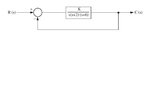
question.JPG

thanks for any help
 

A bode plot is a simple, but incomplete, way to test for system stability. There are also Nichols plots, root locus, etc. The bode plot is based on the fact that the transfer function of a feedback system is T(s) = G(s)/(1+GH(s)), where G(s) is the forward gain, and H(s) is the feedback gain. By observation, one does not have to know a lot about the system, but if you did know the round trip quantity G(s)*H(s) = GH(s), one could guess when the system is potentially unstable.

How? When |GH(s)| = 1, and ang (GH(s))=180 degrees, then 1 + GH(s) = 0. When that happens, the transfer function T(s) goes to infinity (since you are dividing by zero).

GH(s) is often called the "open loop transfer function". So, obviously, you need to know the effect of all the poles and zeros, since they all effect the gain and phase of the transfer funciton. If you leave off a couple poles or zeros, then your gain or phase calculation could be very far off. Since the bode plot is a usable but not complete indication of stability, you do not want to compromise it any further by sloppy calculations.

Maybe your instructor was making the following assumption: it is a simple control loop where most of the poles and zeros are much higher in frequency than the gain crossover frequency?
 
yes he did that .... but its a private case of phase and gain margin ..he did not show the "normal" way ( the one in the link)
I saw answers to questions from tests and they used the "normal" way or guessed/assumed numbers..

+ his way isn't accurate at all


I read what you wrote ( the first paragraph- I know that and I know how to make a graph ... )
its just a dilemma what to do ... do as the instructor said or as the internet says ?


another problem is that I need to make a correction network for gain and phase and he didnot show that + I need something simple ,maby a simple example since in wiki its higher level and I dont need to get into that higher level for now
 

Hi Highlander,

there are clear definitions for the phase as well as for the gain margin:
* PM (phase margin) at loop gain=0dB: Difference between actual phase and -360 deg (including the phase inversion for neg. feedback), otherwise against 180deg.
* GM (gain margin) at phase -360 deg.: Difference between actual gain and 0 dB.

However, these definitions are valid only if the simplified Nyquist criterion applies under the following condition:
1.) Loop gain is stable (no open loop poles in the right hand s-plane);
2.) The loop gain function crosses the 0 dB line only once;
3.) The phase function crosses the -360 deg line only once.

LvW
 

well he didnot mention Nyquist - he didnot even wrote his name lol...
if you look at the image I sent at a previous post in this thread ..does Nyquist aplies there and does the private case that my instructer said is fine or I should do it by the "general" formula like you wrote ?

because the answers are different... and the "general formula"( what you said and what I found online) are much accurate then what my istructer told me to do...

I am in a dilemma since I havev a test about it and i know its not hard but its a bit hard to know which answer will be accpted at the test and which wont.
 

..........
I am in a dilemma since I havev a test about it and i know its not hard but its a bit hard to know which answer will be accpted at the test and which wont.

I think, nobody will resp. can reject an answer that is correct. Perhaps I didn`t get the problem now. But I never have seen a definition for PM and/or GM that inludes pole or zero locations.

---------- Post added at 15:23 ---------- Previous post was at 15:19 ----------

You can use only words to define the margins:
The phase resp gain margin (PM,GM) is the amount of negative phase shift or gain, respectively, that must be introduced into the feedback loop in order to come to the stability limit, which exist at loop gain=1 (real and unity)
 

mm ok... my instructor definition is strange... but as one of the people of commented here wrote:

Maybe your instructor was making the following assumption: it is a simple control loop where most of the poles and zeros are much higher in frequency than the gain crossover frequency?


I understand that a PM and GM are as you said but lets say if I go in the way of my Maybe your instructor was making the following assumption: it is a simple control loop where most of the poles and zeros are much higher in frequency than the gain crossover frequency? for example I have a pole in 40 [rad/sec] and another at 100[rad/sec] and at 100[rad/sec] the gain go under 0 dB to lets say -25dB and the phase goes to 225 degree.

so at the way of my instructer the GM is 25dB and PM is 180-225

but at the general formula like you said the GM and PH could be smaller since its messured differently
for example the PM between 0dB and 180 degree could be 25 instead of 45

just make a small sketch to yourself and youll understand

since if you look from my point of view there are two possible answers one from the instructor and one from the internet
one could be 45 dgree 25 dB

and one could be 25 degree and lets say 15 dB and there is a difference so whats right..

sicne the instructer doesnt check that test its an external test and I am confused.. I have only a few days until that test.


and about fixxing the GM of PM how do I do it there is a formula for that but I need something simple
like adding a pole or a zero ( or adding a zerro or pole at some places) how do I do that...how do I know which W[rad/sec]
I should choose a=or should it be a pole or a zero or a mixed thing


sorry for troubling you so much ;)
 

...for example I have a pole in 40 [rad/sec] and another at 100[rad/sec] and at 100[rad/sec] the gain go under 0 dB to lets say -25dB and the phase goes to 225 degree.
So at the way of my instructer the GM is 25dB and PM is 180-225


If you have only two poles, the phase cannot go to -225 deg. The maximum is at -180 deg.
I cannot follow your argumentation. What is the meaning of -25 dB? At which frequency?
 

Answer to the question stated in the figure.
First choose your pm and then you have an equation for the unity gain of the system.
Arctg(wu/2)+Arctg(wu/6)=90-pm,

From this equation you will find wu and then:
Abs( the system at wu)=1, from this you will find k for specific pm.

---------- Post added at 16:20 ---------- Previous post was at 16:17 ----------

Also there are very good text book on control theory. Just have a look. I think it is better.
 

it was an example .. ok I ll try to make a good example:

let say you have 3 poles and a zero after all the math you get to a degree of -225

and gain of -50 dB at the last W[rad/sec] ( lets say the last one is a pole ( meaning zero-> pole-> pole->pole)

my instructer way to calculate the GM is go to the highest W[rad/sec] in our case its athe 3 pole and calculate the distance between that point to 0 dB.

and his way to calculate PM is : take the last W[rad/sec] in our case its the 3 pole and you got to -225 and do : 180-225=-45 (PM)


but if I do it as I saw it in the internet , I wont get the same answer .
I read that GM you go to the 180 degree and then go up to the graph of dB
calculate the distance between that place to 0dB

like here ( the internet way):
**broken link removed**


so there will be differences in answers it could be a small difference and it could be a large difference but is it acceptable in tests ?

I am not sure the way of my instructer/teacher is right

---------- Post added at 17:27 ---------- Previous post was at 17:26 ----------

I did look in books but there is the way of the books/internet and the way of my teacher and i am not sure whats right
 

Highlander - sorry, but I cannot follow you. One zero and three poles result in a maximum total phase shift of -180 deg. only.
Remember: One single diagram can say much more than 10 sentences.
I repeat: There is only one definition for PM and GM - and I am not able to follow your instructor.
 

Highlander, here is the announced Bode scetch.
Hope it helps.
LvW
 

Attachments

  • Bode_scetch.pdf
    367.1 KB · Views: 49

Status
Not open for further replies.

Part and Inventory Search

Welcome to EDABoard.com

Sponsor

Back
Top